Building a Body
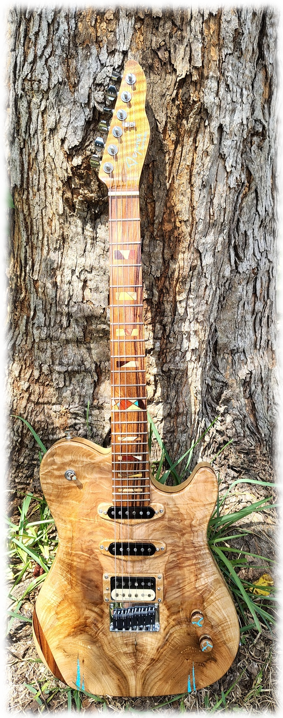
- Modification
date
- Introduction
- Raw materials
- Making
or buying templates
- Gluing the drop top blank
- Cutting out the body
- Making the chambers
- Making and installing control cavity covers and mounting rings
- Rough cutting the drop top and middle layer
- Filling the cracks with crushed turquoise
- Gluing in the middle layer and removing the chamber overhang
- Installing magnets in control cavity covers and mounting rings
- Installing threaded inserts for back pickup covers
- Recessing the underside of the drop top over the pickups
- Shielding the control cavities, pickup cavities, and underside of drop top
- Gluing on the drop top
- Rounding over and leveling the drop top
- Making the pickup mounting rings
- Rounding over the back
- Making
the arm and rib cuts
- Routing
the neck pocket
- Finishing the body with CA glue
- Routing the pickup cavity holes in the drop top
- Positioning the neck and drilling the holes in the neck pocket
- Positioning the bridge
- Making the custom volume and tone knobs
- Drilling
the potentiometer, switch, and jack holes
- Drilling the string through body holes
- Drilling the string ferrule holes
- To pickguard or not to pickguard
- Installing
hardware
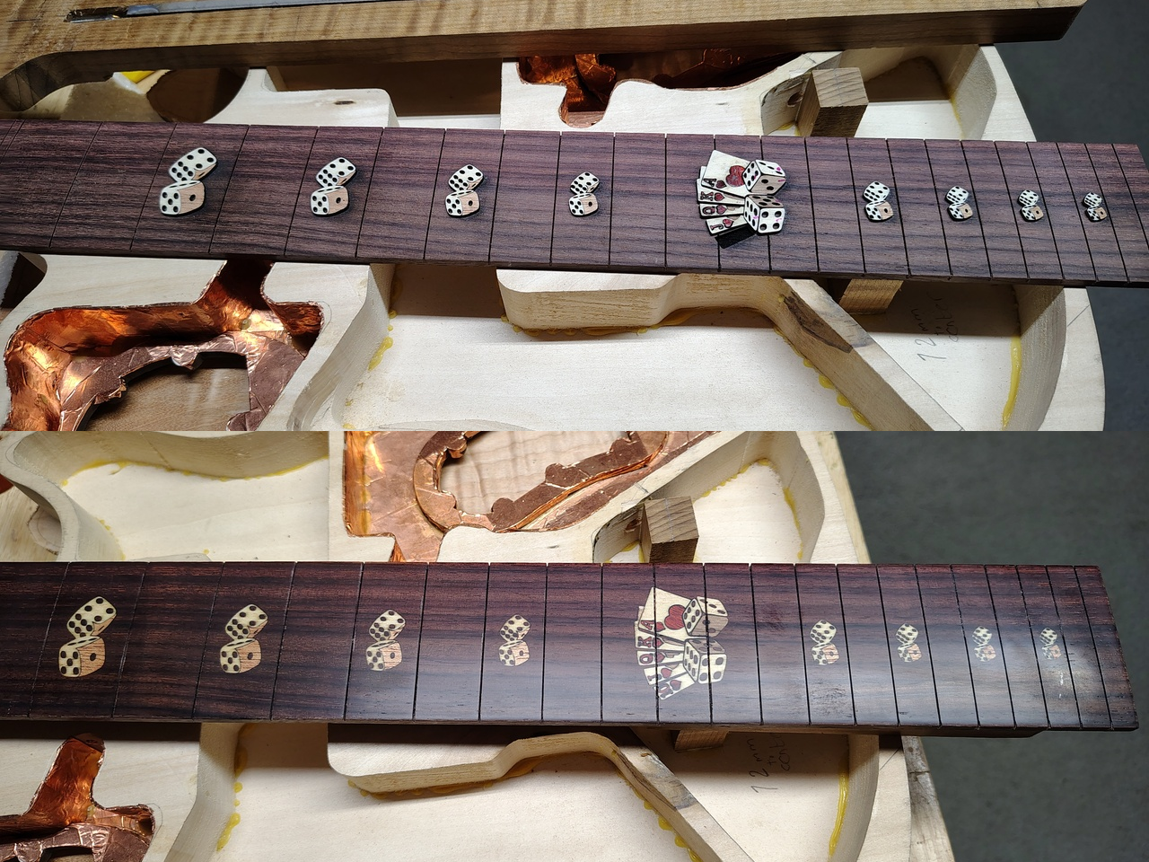
Trying to cut those letters and numbers by hand would drive you nuts. That 12th fret inlay has almost 30 different pieces of wood in it. So, the thing about the laser is - do you want to spend more time making and installing inlays than you do building the entire guitar? Or, possibly - do you want to do dot markers instead of something cool? I still do dot markers on occasion but I almost always do a pretty involved 12th fret inlay. There's a good thing that comes from using the laser - since it won't cut abalone or pearl I'm not using stuff that's getting scarce. I also never liked the feel of large pearl or abalone markers when playing.
Now, on to more important things. This is going to be a very long web page. More like a book than a page. When you've scrolled down in the text or jumped to one of the entries in the table of contents you can get back to the top without scrolling by placing your cursor over the little red thingy on the lower right side of the page. When you do that it will do a Pinocchio and stick out into the page. Just click on it and it will take you to the table of contents.
All of the images, with the exception of the first one, are displayed as thumbnails. If you want to see a larger version just click on the image. It will then be displayed with an X to close it. If that's not enough detail you can right-click on the image and select Open Image in New Tab (at least in Firefox and Chrome) which will just open the full image in a... wait for it... new tab. When you're done looking at it just close that tab.
Since I've been making guitars for quite a while you might think that I don't have any problems building one. Ha! I had a couple of problems with this one but, as Bob Ross used to say, those are happy little accidents.
For example, on an earlier build, I was using the laser to burn the recess for the logo inlay on the headstock and I forgot to turn off the guide lines before I burned the recess. I caught it about halfway across the neck and killed it but it was too late. There was a lovely little line cut half way across the peghead. It was a good 1/16" deep so I couldn't sand it off without making the peghead too thin. To cover it up I made a little 1/8" wide inlay that went around the logo like an outline. I got more compliments on that stupid little inlay than on anything else on the guitar... happy little accident.
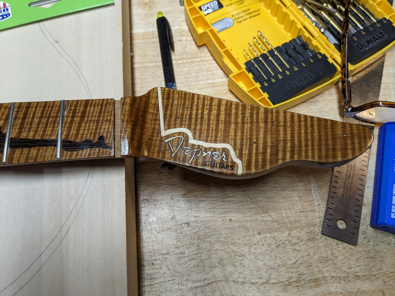
Another thing that happens is that, when trying to write instructions like this, because I've been doing this for a while, I think that "everybody knows that" when, actually, everybody doesn't know that. I'll try to remember to include little things that may seem obvious to me but everybody might not know.
Before you get started you need to take a look at the Tools page to get some idea of what you'll need.
Raw materials
I guess they're somewhat raw. I used to use lumber from a local lumber store and planed it down on my old Sears 6 and 1/4" jointer/planer. Unfortunately, Katrina took that away. Now I can buy body blanks, drop top blanks, neck blanks, and fretboard blanks online. They make things a bit easier but you'll still be building the body from raw wood not prefabricated parts (i.e. a partscaster). For this particular build I've got a drop top blank, a body blank, and a middle layer blank.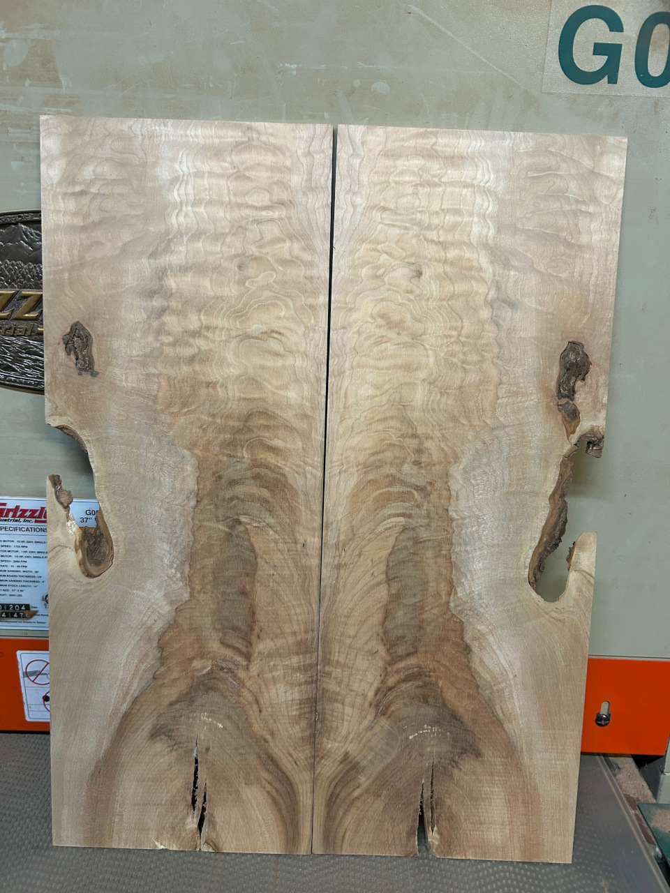
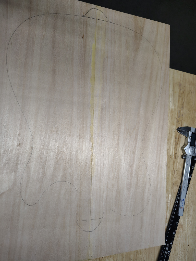
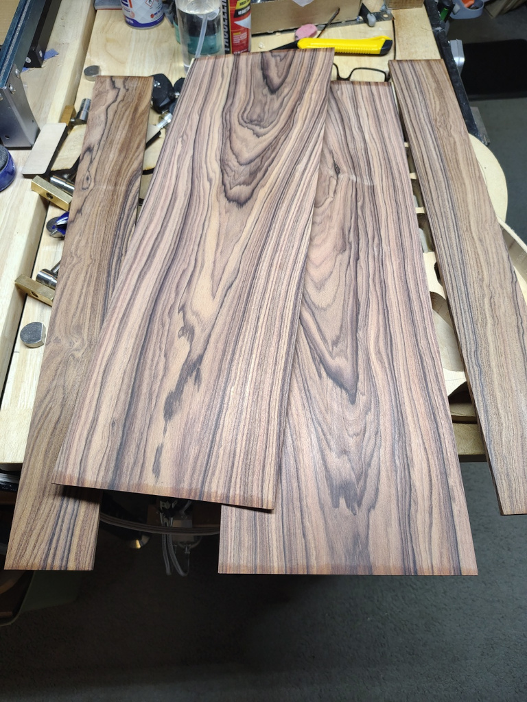
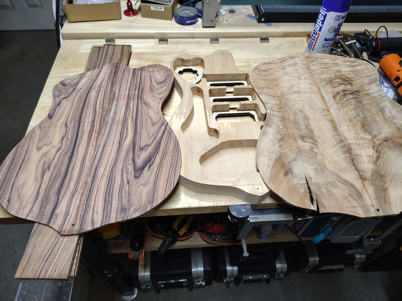
The drop top wood is quilted, flamed, checked maple from Oregon Wild Wood. There are many more sources of drop top blanks, I've used Kimball Hardwoods and North Ridge Hardwoods (way expensive). The body blank is basswood from American Specialty Hardwoods or you can get one from Keim Lumber. The middle layer (the two 1/8" pieces in the middle) are Bolivian rosewood from Ocooch Hardwoods. You don't need to use a middle layer but I kind of like the way it looks when I make the arm cut. You can also just bend the drop top where you need the arm cut. It can be a bit tricky with highly figured wood. You can see how that's done in the old documentation, specifically, boxes 14, 18, 21, 28, 29, and 30.
Making or buying templates
You have a choice here. You can either make you own templates out of 1/2" MDF (which Home Depot will deliver to your door for free) or you can buy templates. There are tons of places to buy templates but they're not cheap. I prefer to make my own. There are a bunch of scaled template drawings on Electric Herald. Most, if not all, of them are in PDF format. You can use Adobe Acrobat to print them out in poster mode so you can tape them together, cut them out, then trace them onto MDF. Sorry, this doesn't work on Linux. The really good thing about making your own templates is that you get to make whatever shape you want.I've found a few other templates online. Some of them are even to scale. If they're not to scale you can load them into GIMP, look at the Image->Scale Image settings, compute the number of pixels for a known distance (like nut to 12th fret), then scale the image to make that work out correctly. Unfortunately, you have to do some math to do that. So, for example, let's say you've found a Strat template. Open it in GIMP, right-click in the image and select Image->Scale Image. Looking at the X and Y resolution we see 300 pixels per inch (or 11.811mm per inch). Measure the distance from the face of the nut to the middle of the 12th fret using Tools->Measure Tool. For this example, let's say that distance is 3000 pixels. To convert that to inches just divide 3000 by the pixels per inch. That is, 3000/300 = 10". Since the Strat has a 25.5" scale length, the distance should be 12.75". From that you can compute that the distance in pixels from the nut to the 12th fret should be 12.75*300=3825 pixels. So, what we have now is a ratio. The ratio is, what it should be (3825), divided by what it is (3000), or 1.275. Once again, right-click and select Image->Scale Image then multiply the Width value by 1.275 and enter the result in the Width field, tab to the next field (which will set everything you need), then click on the Scale button. After you do that double check your distance.
Here are a couple of neck templates in PNG format. They are 100 pixels per inch. You can import these to Lightburn or convert them to PDF and poster print them from Adobe Acrobat. They both have generic, 10mm, 6 inline tuner holes and a block peghead that you can modify in GIMP to a better shape. I mean, I wouldn't encourage you to copy any Fender headstock designs since they're copyrighted. The first one is a 24.07" conversion neck. There will be an overhang of the fretboard at the end but that will allow it to be put into any stock Fender style body. The second is a Fender standard 25.5" scale neck.


Important note: The heels of these neck templates are "Strat" shaped so that they will fit either a Strat style rounded neck pocket or a Tele style square neck pocket.
At this point I'm going to put in a link to my multi-layer TIFF guitar body design file. The layers have color-coded registration marks in each corner. Working with multi-layer TIFFs in GIMP is the easiest way to build your design and make sure everything fits. The file is Tele_shorthorn_HSS.tiff. You can right-click on that link and select Save Link As... to save it into a file. Open it with GIMP and turn the layers on and off to see everything. To export a layer to a PNG or PDF file for use in Lightburn or Adobe Acrobat, respectively, select the layer in the lower right, press Ctrl+C to copy it, select File->Create->From Clipboard (or save some time by pressing Shift+Ctrl+v), select File->Export As..., then save it as a PNG or PDF file.
Gluing the drop
top blank
So, now you have the tools, the materials,
and the template(s) and are ready to go. The first thing
you need to do is to glue the book-matched drop top
together. Before you can do that you need to clean up the
edges that are going to be glued together. I’ve seen a
number of ways to do this. One is to set up a shooting
board and use a large block plane. Now, I don’t have a
large block plane so what I do is to tape the two pieces
together face to face with some masking tape, pencil mark
the edges that will be glued together, place a piece of
peel and stick 220 grit sandpaper on a large flat surface,
then hold the two pieces upright and sand the edges flat.
You can also put peel-and-stick sandpaper on a long flat
piece of wood, lay the taped up pieces on a flat surface,
and use the flat piece of wood as a sanding block (this is
actually easier to keep straight). Just keep checking the
pencil marks until they’re all gone. Once you’ve got the
edges flat and they join together with no gaps it’s time
to glue the pieces together. Methods vary but the best and
easiest that I’ve seen is J.
S. Bogdanovich’s method. Note the little wedges in
the bottom of the photo. I got that method from
Bogdanovich. Like Jimmy Buffett (and/or Lord Buckley)
said, "it was so simple, like the jitterbug, it plumb
evaded me". You don't really need an excessive amount of
force to glue these together so the little wedges provide
plenty of pressure.You can also put a strip of wax paper
across the top and clamp a very flat board over the seam
to make sure it's flat.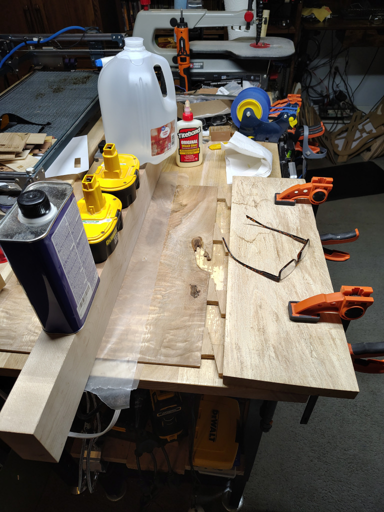
If you buy your body blank from American Specialty Hardwood you will also have to glue the two pieces of the body blank together. That's pretty easy with a couple or three bar clamps. Conversely, you can pay them $15 extra to do that for you. If you use a middle layer you'll need to glue that together as well using the same technique as the drop top.
Cutting out the body
Now that the drop top is ready to be cut out you can start on the body blank. Plane the body blank down to 1 and 1/2" using the StewMac Saf-T-Planer or a regular planer if you have one. This assumes that your drop top is 1/4” thick. You’re shooting for 1 and 3/4” thickness so adjust as needed. Next you should rough cut the body shape out of the blank. Leave a couple of tabs at the top and bottom to be used for attaching the routing template and, later, the drop top.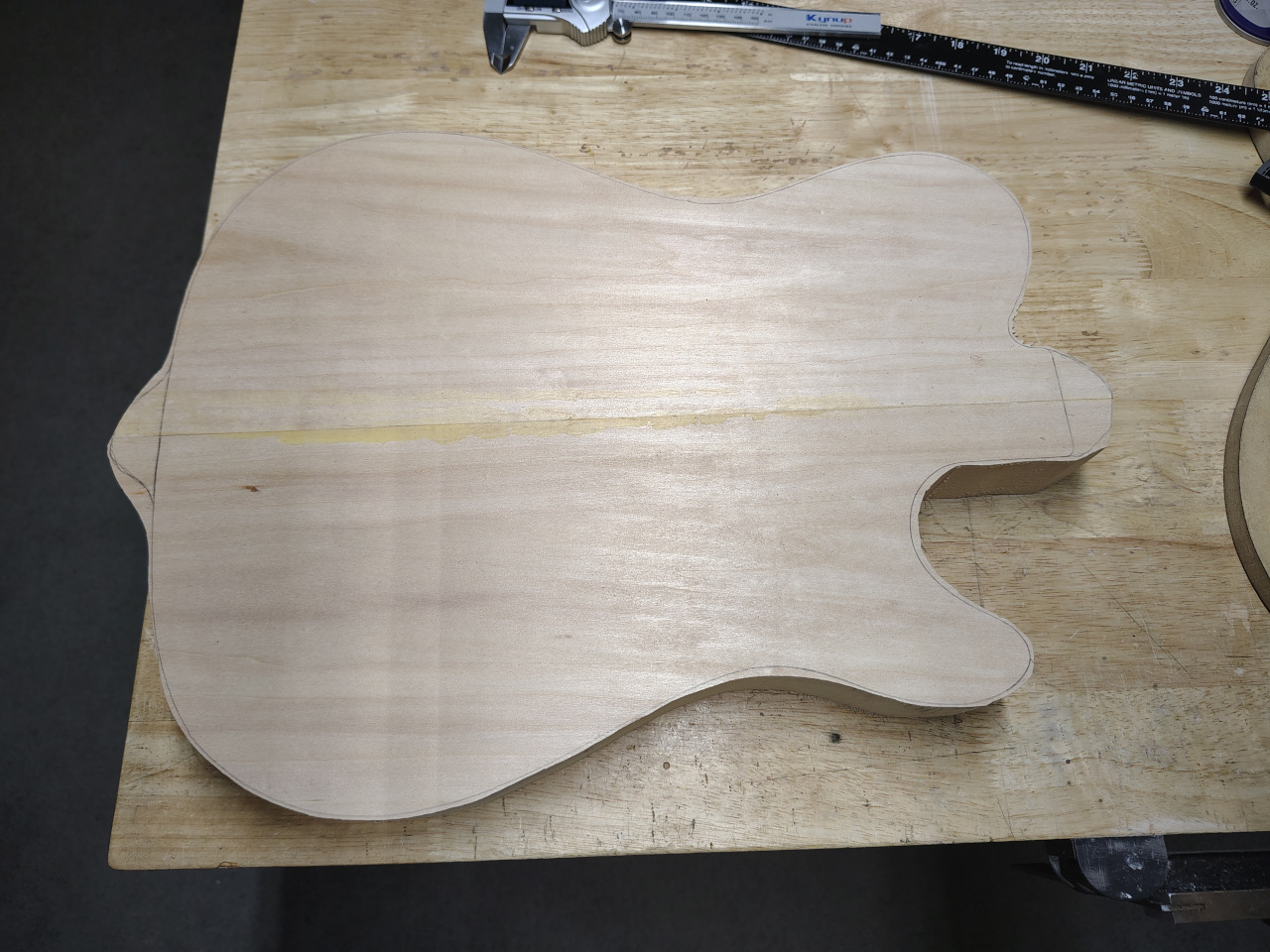
Making the chambers
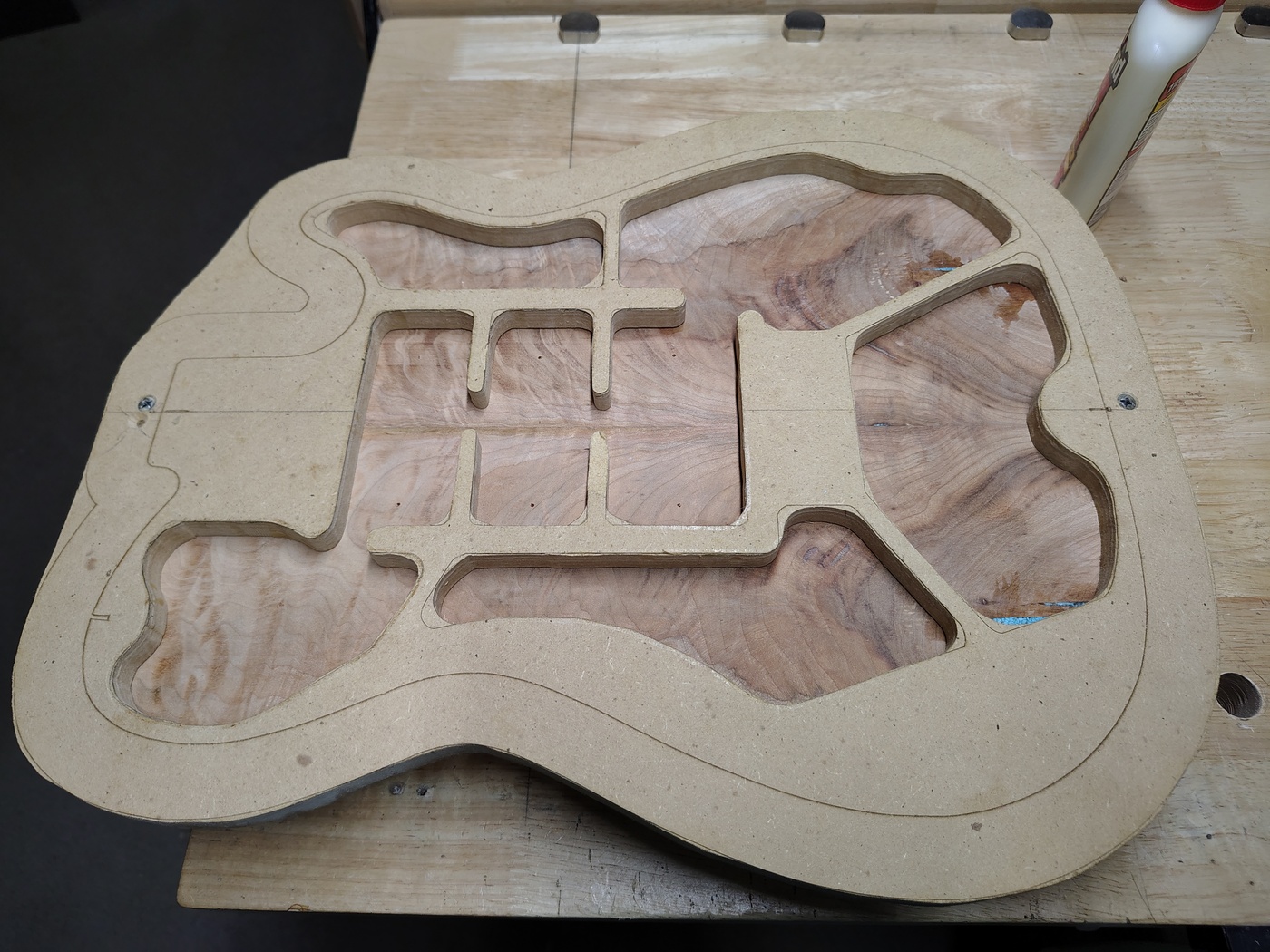
Next you need to rout the chambers. One very important note - you need a large router base to do this. I made my own from a 7" piece of plexiglass that I got on Amazon. At the time I did that, large router bases were about $40. Now you can get a 6 and 5/8" generic router base for $20. It's worth the extra $10.You can design your chambers any way you want for the most part. When I first started making “Thinline” single cutaway style guitars I went with the “normal” chambering as it was done on the original Thinline Telecasters. That amount of wood left in the guitar body is pretty much overkill. As I made more guitars I kept thinning the back and sides until I finally ended up on 1/4” back, sides, and top. As long as you leave in some structural support (like the “ribs” in third picture) you’ll be fine. Unless you decide to run over the guitar with a truck or go all Pete Townsend on it you won’t have any problem with strength. When you put 1/4” of maple on the top it becomes incredibly rigid (as if it wasn’t already). This is called “skin strength” and works in much the same way unibody construction works in vehicles.
To rout the chambers you'll need a template. Here you can see the template that I made and the roughed out body blank with the chambers marked in pencil. You can also see the countersunk screw holes in the template at the top and bottom as well as the holes in the blank. I drilled the two holes in the template, lined it up with the blank, clamped them together, then drilled the holes in the blank. I use sheet rock screws to hold them together for routing.
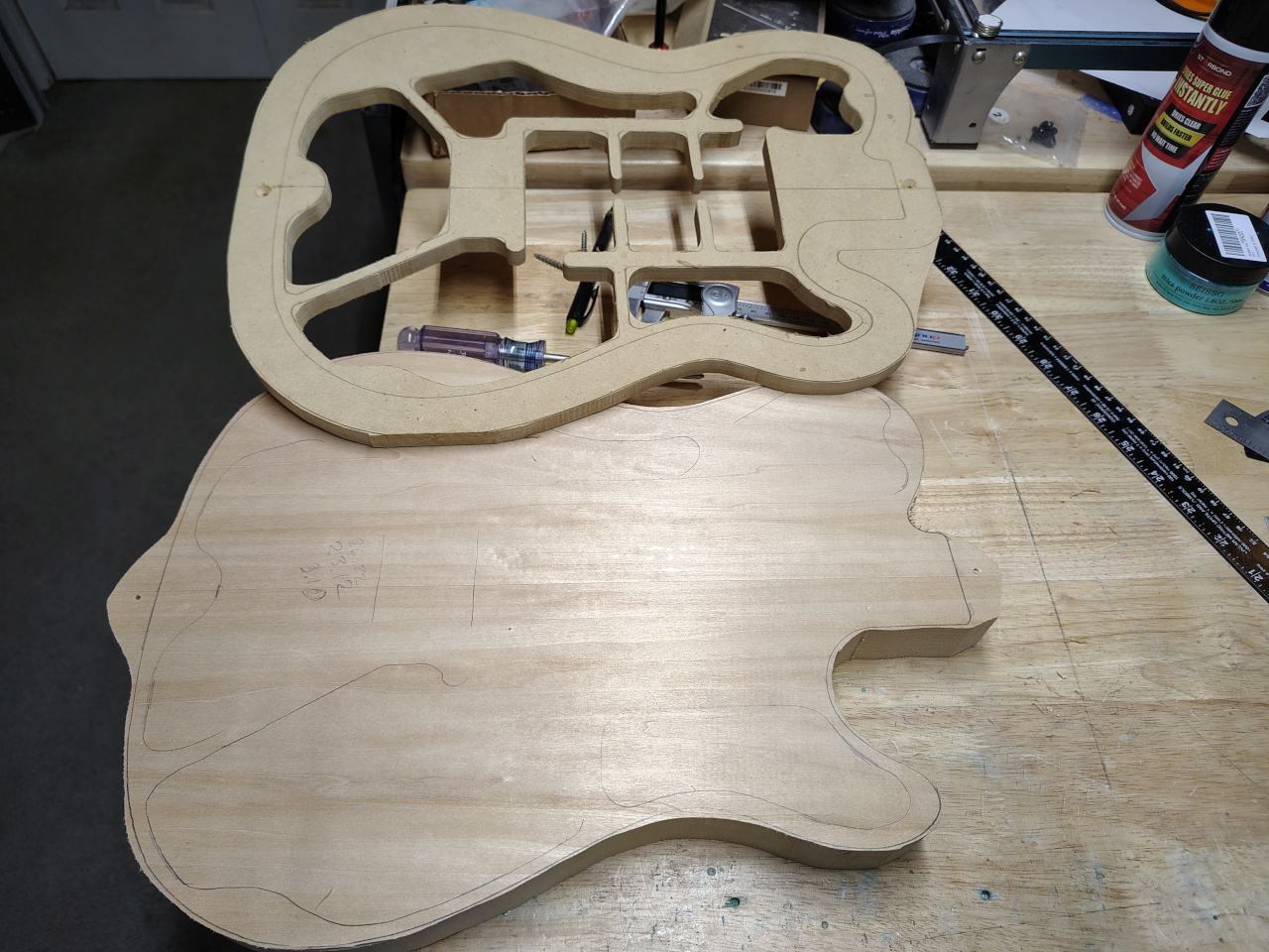
You can just use a router to take out the wood in the chambers but your router will get pretty hot doing it that way. I prefer to use a fairly large Forstner bit in my drill press to hog out the majority of the body before I start routing.
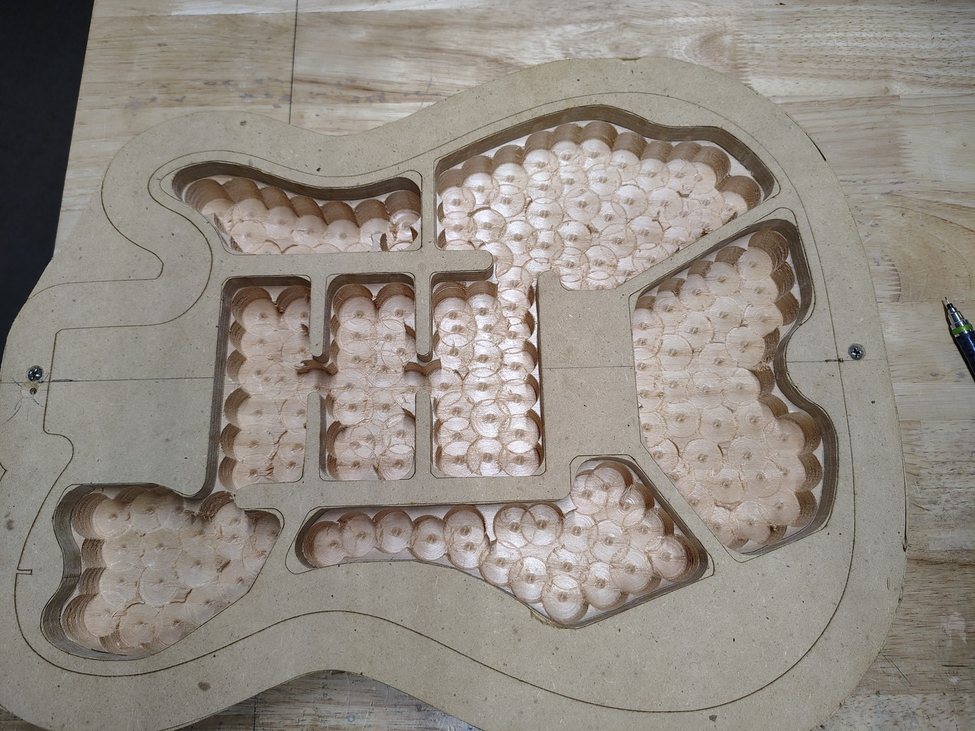
After you've gotten rid of most of the wood you then rout the chambers to their final shape and depth using a 1/2" top bearing flush trim router bits. You'll end up using all four of the ones that come in those sets from Amazon. Don't try to take too much off in one bite.
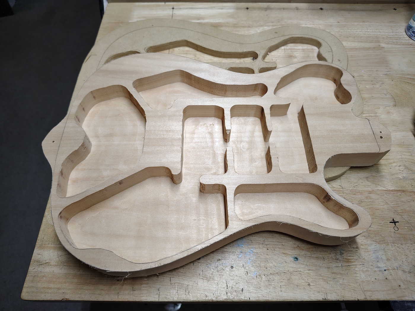
After routing out the chambers you can clean up the outside of the body blank. I used to use my body template and rout it but I found that it was just as easy using the oscillating drum sander to sand it to the outline (from the body template). One big advantage to doing it that way is that you'll never get any tear-out or chipping with the sander. I knocked a big chunk off of one of my earlier guitar bodies and had to glue it back in and clean it up. There was some serious French being spoken at that point. If you look closely at the previous picture you can see a couple of places where the router knocked a chunk out of the internal "ribs". Not a big problem because they'll only be visible by looking in from the back of the guitar and they'll be covered in copper foil tape.
Making and installing control cavity covers and mounting rings
Next you need to cut out access holes for the chambers that are going to hold the controls. I always use a Les Paul style switch in the upper bout because it’s so much easier to use when you’re playing live so I have two control cavities. Also, in this instance, I planned to back mount all three pickups so there were three more cavities to deal with.
Since I used my laser to make the control cavity covers and cut out the openings, I'll cover that first. But later on I'll discuss how to do this without a laser.
You should have planned out where your control cavity access holes and covers go (obviously, since you've already routed the chambers). Looking at the TIFF file in the templates section above, you can see the design of the cover mounting rings. I used to rout all the cavities to 1/4" except where the covers go. I would leave that at 1/2" so that I could cut out a mounting shelf for the covers. I have more recently found that it is much easier and faster to just make basswood mounting rings (using 1/4" thick basswood from Ocooch Hardwood) and cut the access holes into the 1/4" back. I cut my mounting rings with the laser but it's just about as easy to use a jig saw or scroll saw to cut them. They don't have to be perfect since they'll never be seen.
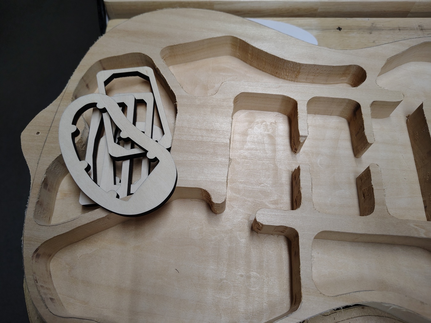
Next you need to cut the covers out of the back of the blank. If you have a laser this kills two birds with one stone by making the cavity covers and cutting the access holes at the same time. Using Lightburn you need to import the Rout layer of your TIFF file (assuming that you've modified the TIFF file from the templates section). You also need to import the Cavity covers layer. Both of these layers need to be inverted because we'll be working on the back of the body. Lay out some paper, poster board, or cardboard on your laser platform, set the height, and draw the Rout layer on the poster board (probably 1800mm/min, 25%, 1 iteration). Once that's done, VERY CAREFULLY put the body blank upside down on the laser platform and set the laser height. Don't move the laser in X or Y or you get to start over. Once the height is set, position your body blank on the drawing (face down, obviously), and cut out the cavity covers. Now, here's a massive caveat that I learned the hard way - you need to put aluminum foil inside the cavities and tape it in place. If you don't, at some point when you're cutting the covers, they will fall through and you'll get a not-so-lovely line cut across them.
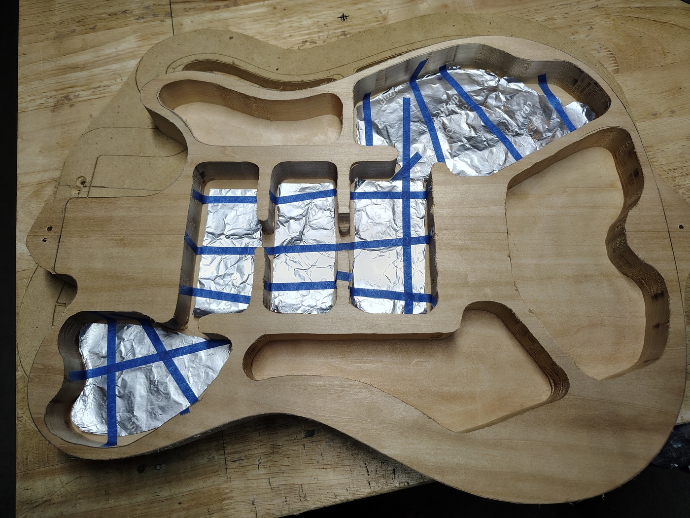
Once you've got everything lined up, pray a lot and then cut the covers.
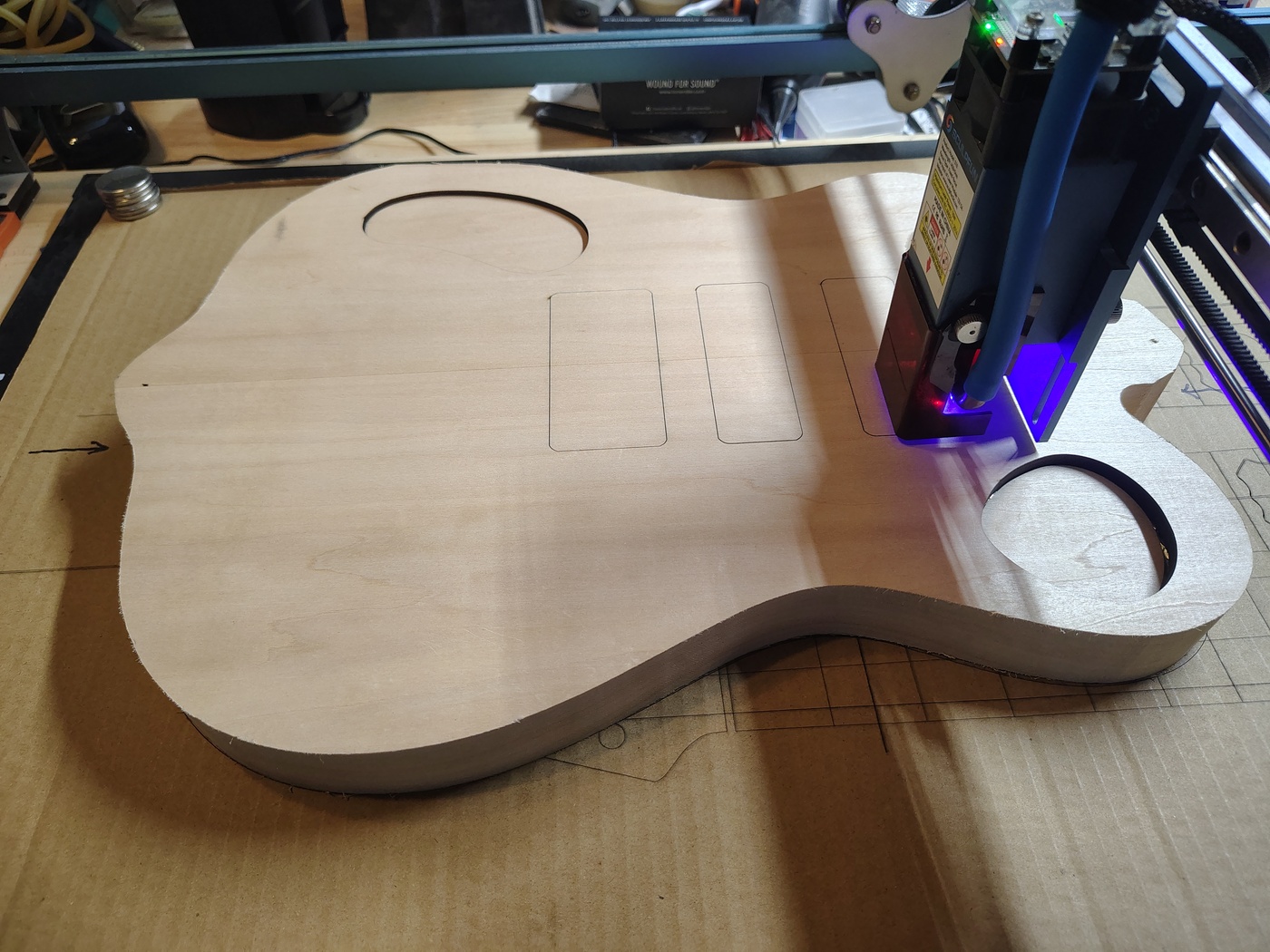
On the bright side, if the covers do happen to fall through (like the switch cover almost did in the above image) you can always make new ones using other pieces and/or types of wood (figured maple works well and is very pretty) using the manual method described below.
Now, supposing that you don't have a laser and you need to do this by hand, it's not that hard. The easiest way to do this is to make cover plate templates out of MDF. It is best to not make them symmetrical because it can be difficult to figure out which way they go on after you take them off. I use a teardrop sort of shape for the switch cavity and a kidney bean shaped cover for the potentiometer cavity.
Make sure that they fit in the chambers that they are used for and allow enough room for a mounting ring in the cavity. You’ll also want to make sure that you have enough room to get the components in and out after you glue in the mounting ring. It’s best to make some mockups out of paper or cardboard before you start hacking on anything. So, use the cover plate templates that you’ve made to rout through the bottom of the guitar into the requisite chambers. The best way to figure where you want the cover plates is to drill through from inside the body blank in the locations that you want your switch and pots. That way you can make sure that you can get the electronics in and out easily. Next, use the same templates to draw the cover plates on whatever you want to make them from. Using leftover parts of the drop top wood is kind of nice but you can also use basswood veneer. Just cut close to the edges of the design then sand (oscillating drum sander works great for this) and test fit until it’s right. In the following picture you can see the cover plate supports have been glued in to the control chambers. The little bumps on the supports are for 3X5mm neodymium magnets to hold the cover plates on (more on that later). I used inserts and machine screws to hold the pickup cover plates on. I just didn't want to use magnets right below the pickups. Since magnetism decays according to the inverse square law (and, off center, up to inverse cube) it's probably not necessary.
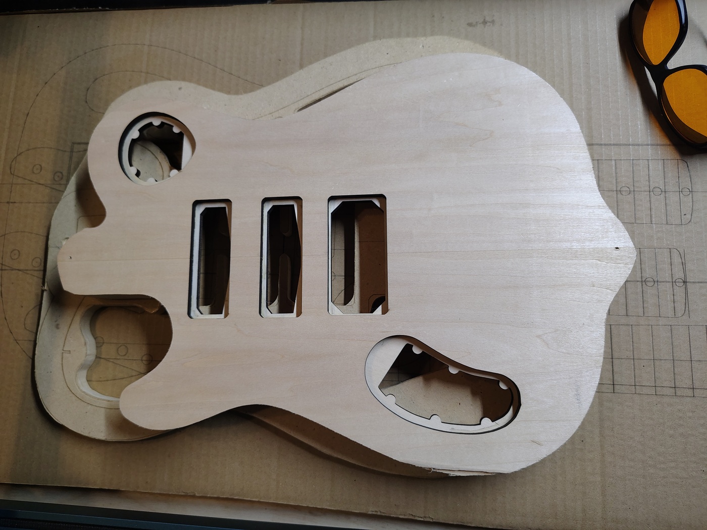
One important note - if you look at the control cavities you'll see that there is a ledge in the end of each of them. On the covers you need to sand an angle on the corresponding areas so that you can push down on that spot to pop the cover off. The easiest way to do this is to place the cover in the recess and then trace the ledge on the cover. Then all you have to do is sand it at an angle. It doesn't have to be too deep of a cut. Keep checking it until it works and then quit sanding.
Rough cutting the drop top and middle layer
Set the guitar body, upside down, on the drop top blank. Line up the center lines on both ends. Trace the body shape, including the top and bottom tabs onto the drop top blank (also upside down). Using a jig saw, scroll saw, or band saw, cut around that outline leaving about 1/4" outside of the outline. Place the rough cut drop top on the top of the body blank, line it up with the body blank center line, clamp it in place, and redraw the top and bottom tab outlines on the drop top blank. Unclamp everything, flip the body blank over, and, somehow, figure out where the screw holes are on the tabs. I just measured it but it might be easier to take a piece of paper, trace the tab outline from the body blank on it, cut it out, place it on the body blank, punch a hole where the screw hole is, then place it on the drop top blank and mark the screw hole (wish I'd thought of this earlier). Drill the screw holes in the drop top blank and test fit it on the body blank with the screws. You might have to drill new screw holes if you didn't get it lined up correctly. Once everything is good, countersink the screw holes in the top of the drop top.
If you're making a middle layer you can rough cut it the same way as the drop top then use the drop top to mark the screw holes. Drill them but don't countersink them.
Filling the cracks with crushed turquoise
Here's something that is just relevant to this specific build. If you look at the drop top in the Raw Materials section you can see that there was a perfectly clean area of the blank that I could have used. Lovely quilted maple with no defects. What fun is that? So, being Abby something, I decided to use the other end. Obviously, there are a few gaps in that end. I decided that it would be nice to try to fill those with crushed turquoise (Amazon or Ebay or Etsy). I'd never done this before but it didn't look all that difficult.
I first taped wax paper over the top of the cracks so that I would have minimal sanding to do on the top.
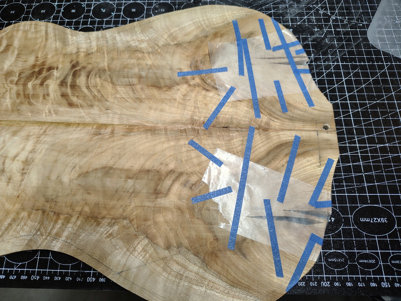
I also made sure that the wax paper covered the ends of the open cracks so that the crushed turquoise wouldn't fall out.
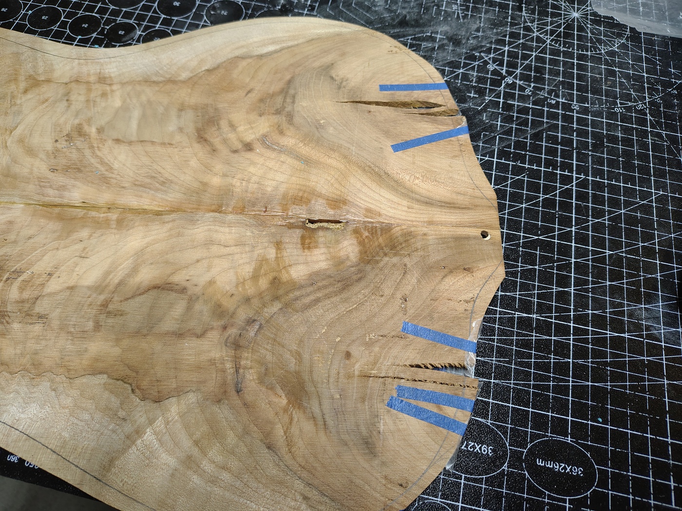
Next I put crushed turquoise into the cracks from the back. I should have crushed up some of the turquoise to a fine powder to fill the real skinny sections of the cracks. Oh well, hindsight is 20/20.
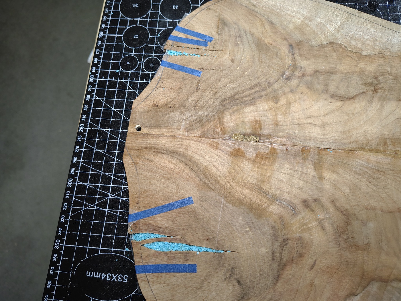
Finally, I soaked the crushed turquoise with CA glue. Since I was planning on finishing the guitar with CA glue this wasn't a problem. If I had been going to finish it with something else or stain it I would have used epoxy since it doesn't soak into the wood.
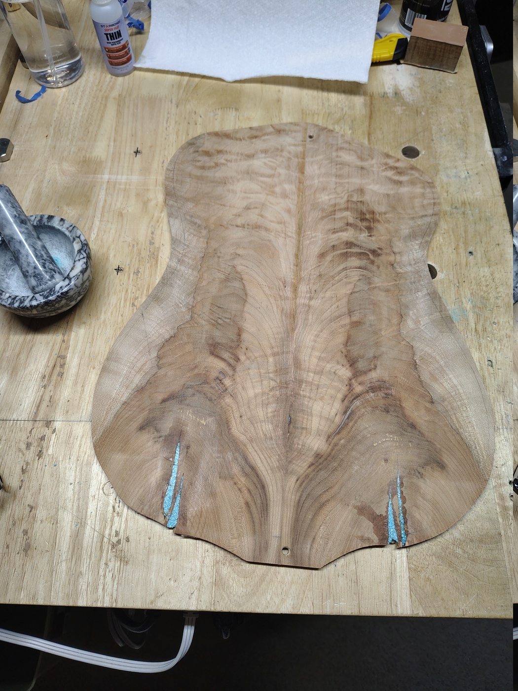
Note the mortar and pestle in the above image... hindsight.
Gluing in the middle layer and removing the chamber overhang
If you're not going to put in a middle layer then this section is irrelevant. To start, I took the chamber template and screwed the middle layer blank to it. I tried to make sure that I got the prettiest piece where the arm cut was going to go. I then traced the chambers on the blank. Next, I rough cut the chambers out of the middle layer leaving about 1/8" of overhang. Once that was done I test fit the middle layer to the body blank to make sure everything was lined up correctly. I used the body template as the back clamping caul and the chamber template as the top clamping caul. I spread Titebond Original glue on the top of the body blank, trying not to be too sloppy, then clamped the whole shebang together.
After the glue dried I unclamped the templates and, using a 3/8", bottom bearing, flush mount router bit, I routed off the excess overhang. I didn't really need to do this but why carry extra weight if you don't have to.
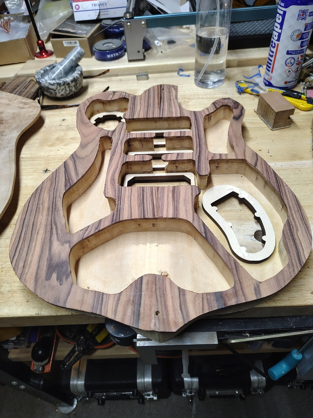
Installing magnets in control cavity covers and mounting rings
Time to install the 3x5mm magnets (I used to use 2x5mm) in the cover plates and cover plate mounting rings. It's a fairly straightforward process. First, you need to drill some 3mm deep recesses in the cover plate mounting rings using a 5mm brad point bit. Make sure you set a depth stop or put some tape on the bit. They won't work right if they're too shallow but they won't have as much pull if they're too deep (inverse square law). The bumps in my TIFF file are 8mm so you should have enough room to easily mount a 5mm magnet in the dead center. Be very careful drilling these. Go slowly because they can break off while drilling. Once you've glued in the magnets the CA glue will soak into the wood and harden them up some.
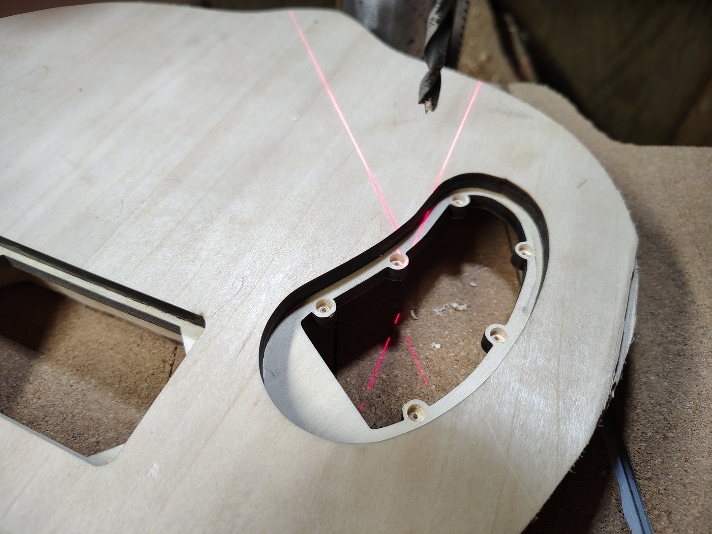
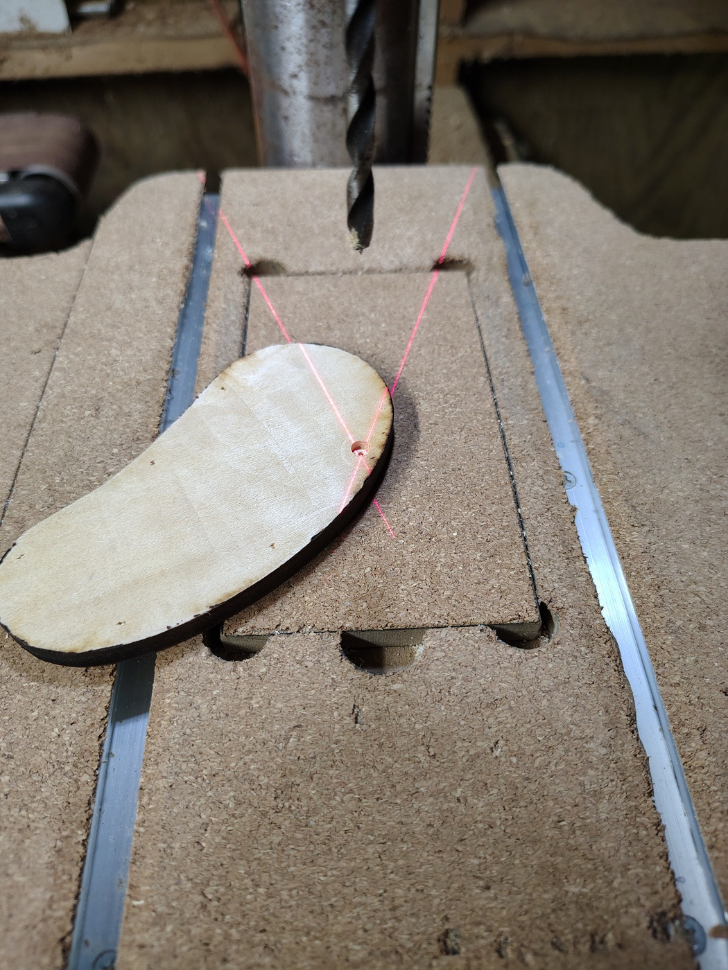
After drilling the 5mm recesses you need to drill a 1/16" hole right in the center of the recess. This is easy to do since the brad point bit leaves a tiny little indentation in the center.
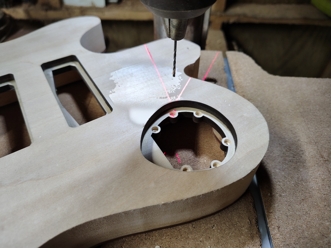
Once those holes are drilled you need to mark the cover plate magnet locations. Place the cover plate in the cover plate recess then push the 1/16" drill bit through the holes that you just drilled to mark the magnet locations on the plate.
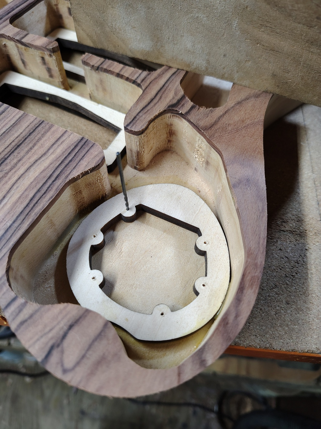
Now, drill the 3mm deep by 5mm magnet recesses in the cover plates. Again, either use a depth stop or put some tape on the drill bit.
Insert the magnets in the mounting ring recesses and put a drop or two of thin CA glue on them. When that is dry drop a magnet on top of each of these magnets. Don't worry, they'll orient themselves. Once they are in place, mark the top of these magnets. In this case I used a white paint pen but a black or blue Sharpie works better.
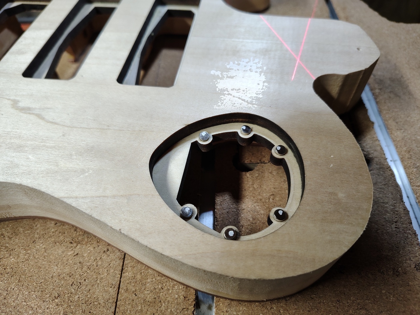
Finally, take these magnets and place them into the recesses in the cover plates. Make sure that you get them in the correct holes in case you put some of the mounting ring magnets in with a different pole pointing up. Also make sure the mark on the magnet is down (i.e. not visible). When those are in place put a couple of drops of CA glue on them. When that's dry, test fit and you're done.
Installing threaded inserts for back pickup covers
This is something I had never tried before. Usually I just slap the normal pickguard screws into these things and call it good. In this case I wanted to be elegant! This time I used threaded inserts and machine screws. Seriously though, there is a major advantage to using inserts and machine screws - you don't have to worry about wearing out the hole like you do with wood screws. What I used was stainless steel threaded inserts with an interior size of M2-0.4, an exterior size of M4-0.7, and an overall length of 4mm. For machine screws I used M2 x 10mm Phillips drive, flat head, stainless steel, machine screws. These are available on Amazon.
Putting these things in was no picnic. First, I had to mark the locations on the pickup cover plates and drill a 1/16" hole through all of them.
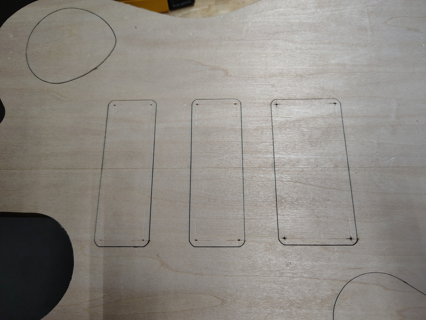
Then I had to drill larger holes in the mounting rings to take the threaded inserts. It turned out that the closest match I could get was 1/8" but that was a little tight. To fix that I used a reamer to open up just the beginning of the hole so that I could get the inserts started. One they started it was no problem since basswood will compress easily enough. You have to make sure that you keep the inserts as straight as possible.
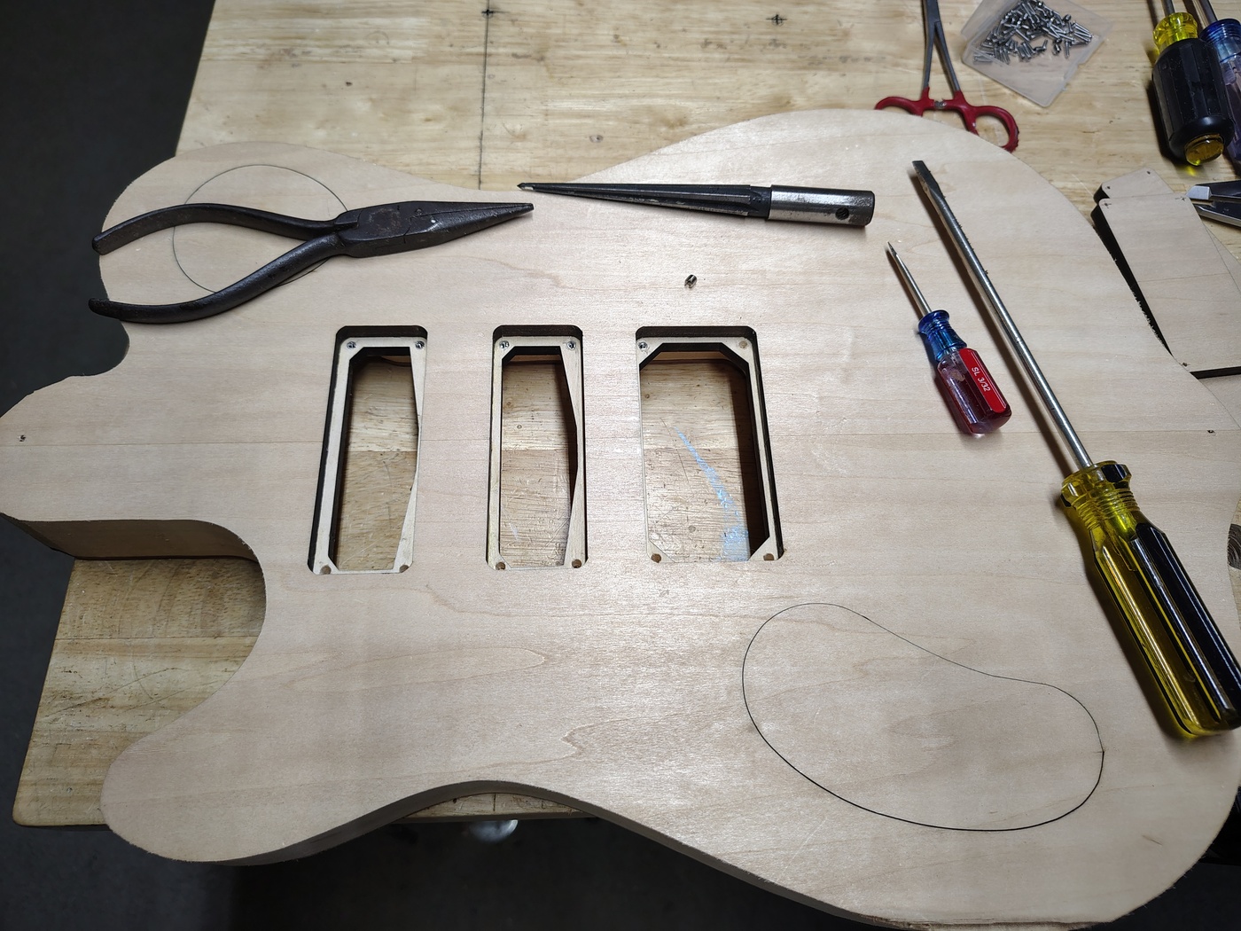
Once the threaded inserts are installed you can attach the cover plates. I didn't even try to countersink these because they are so small. I just let the screw head make it's own countersink.

Recessing the underside of the drop top over the pickups
This became pretty much a waste of time in the long run but the plan was that I would mount the pickups from the back with no mounting rings. Because of that I wanted to thin the top where the pickups were going to be mounted so I could get them close enough to the strings. If they weren't close enough I could always inlay the bridge and recess the neck pocket another 2.5mm. I had done this before on the "stealth" guitar that is covered in A Tale of Three Guitars. Recessing the bridge and lowering the neck makes playing the guitar more comfortable for me, YMMV.
The first thing I did was to attach the chamber template to the underside of the drop top and trace the chambers. This would be needed for shielding the cavities no matter what. I then marked out the areas of the pickups and routed them down 2.5mm with my Dremel tool and the StewMac router base.
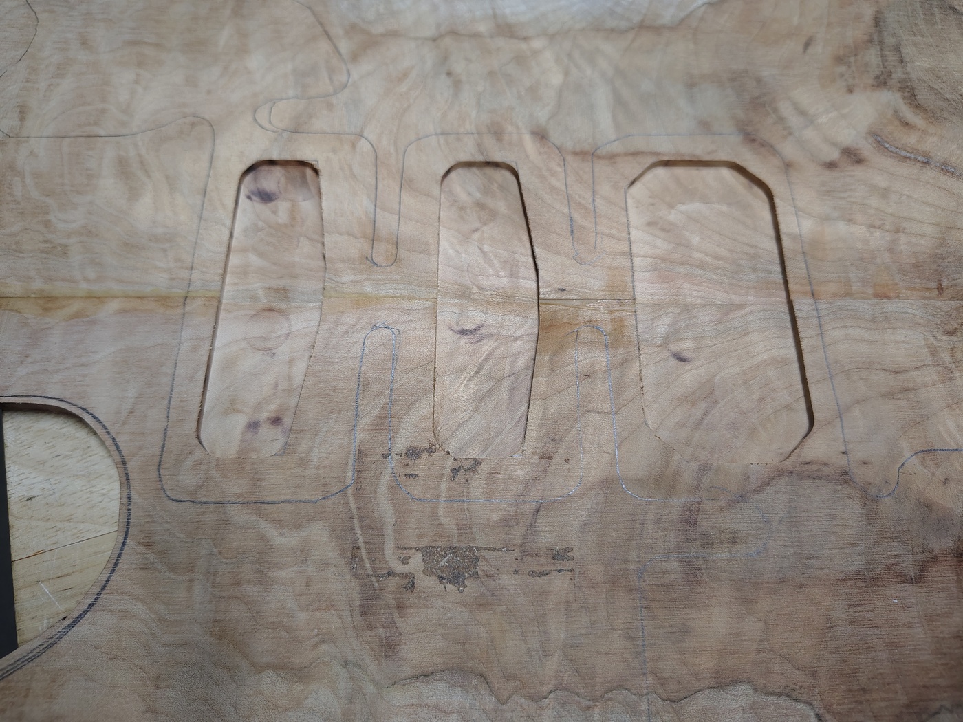
In the end this turned out to be a waste of time but we'll get to that when we discuss leveling the drop top.
Shielding the control cavities, pickup cavities, and underside of drop top
The purpose of shielding the control and pickup cavities in a guitar is to prevent external electromagnetic interference that can cause noise. The way that is done is by making the cavities into what is known as a Farady cage or shield. A Faraday cage is just a grounded cage around electronic equipment. To quote Wikipedia "they shield the interior from external electromagnetic radiation if the conductor is thick enough and any hole is significantly smaller than the wavelength of the radiation". Now, I have worked on many guitars that have the black "shielding" paint in them. I have tested every one for connectivity with a digital VOM (volt-ohm meter) and none of them have shown any connectivity farther apart than about 1/4" (and that was the best, most had zero connectivity). My advice is to never use that garbage.
I use copper foil tape. It is very inexpensive and works great... if you get the right kind. A friend of mine gave me some copper foil tape that was way too thin and the adhesive sucked. I threw it away. I have been using Kraftex Copper Tape that I got on Amazon for a few years now and it's the best I've used. It is kind of a pain to put in but after a while you get good at it. So, the first thing I needed to do was to shield the cavities in the body. You want a little bit of the shielding to lap over the middle layer in a couple of places. That provides a contact to the drop top once it's glued in.
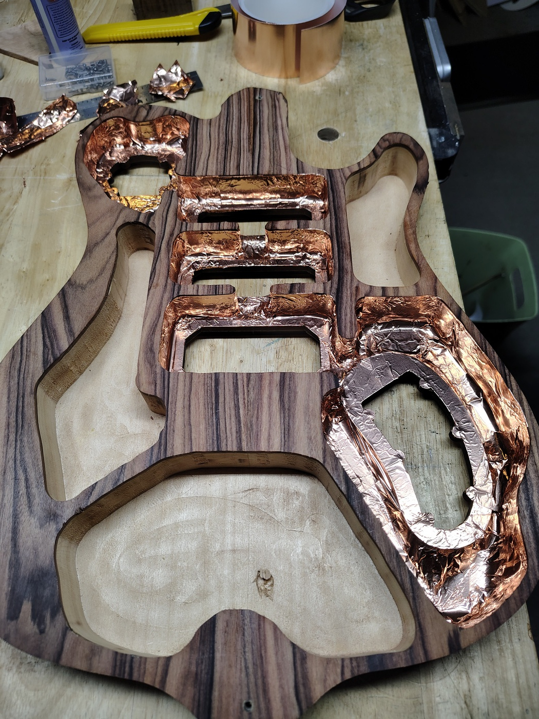
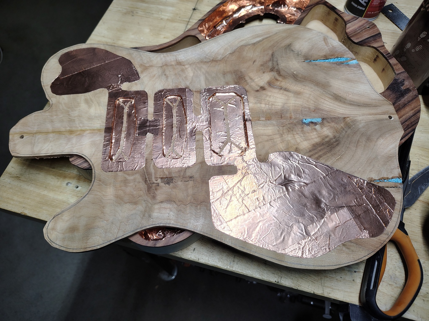
After that I needed to shield the undersides of all of the cavity covers (very easy) and then shield the underside of the drop top over the cavities. I had already drawn the chambers on the underside of the drop top so all I had to do was put copper foil tape on it, put the chamber template back on it, mark the control and pickup cavities, and then use a razor to cut out the shapes.
Gluing on the drop top
Woo hoo! This is where it starts to look like a guitar! So, you've got the top rough cut to very close to the final shape and you've got it shielded. Time to glue it up. Before you even put one drop of glue on it though you need to screw it down to the body and test clamp it to make sure you know what your plan is. Once you've got that straight you need to take the clamps off and put glue on the top of the body.
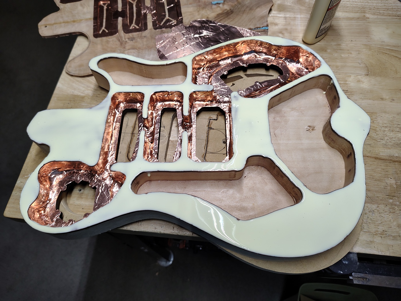
Yeah, I might have been a little overzealous with the glue but at least all of the gluing surfaces are covered. Next you need to screw the drop top onto the body.
Apply a little pressure by hand and then clean up the glue that squeezes out around the edges. Next you have to clamp it down.
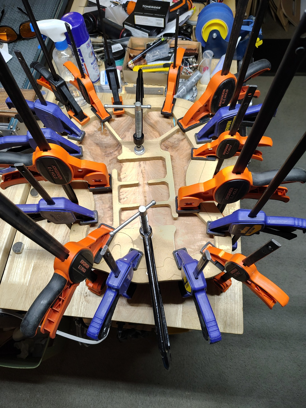
Yep, there's no such thing as too many clamps. Give the glue at least 8 hours to completely harden because the next step is to clean up the drop top edges a bit. I used the 1"x2" Robo-Sander (available at Klingspor Abrasives) to get it to about 1/32" from the body edges. Following that you can cut the top and bottom tabs off of the body and use a router with the body template or an oscillating drum sander (much easier) to clean up the edges in those two places.
Rounding over and leveling the drop top
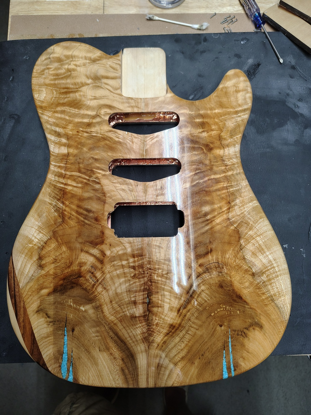
Okay, here's what we've all been waiting for... the not so happy little accident. I had previously made an acoustic/electric guitar (A Tale of Three Guitars) with a highly figured quilted maple drop top. The top ended up being just a little over 3mm thick. I had used my spiral thickness planer to level the top of that and I assumed (you know what they say about that) that I could do the same with this top. Unfortunately, I didn't think about the fact that I had thinned the area where the pickups go down to 2.5mm. DOH! When I ran it through the planer, the three lovely little tear-outs that you can see in the next image occurred. This image also illustrates "bump cutting" while rounding over the top. Where the grain runs against the rotation of the router you carefully bump the bit against the edge and create this scalloped effect. That way, when you run the router back through it against the grain, it can only tear off very little pieces. You'll also note that I wet the guitar before I started routing. This is supposed do help prevent tear-out. I used a 3/8" bottom bearing roundover bit to do this.
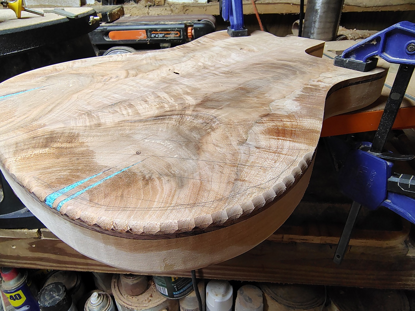
Also in the image you can see the pencil marks I put on the top for leveling the top the old fashioned way. The next image shows the body (before rounding over) sitting on top of my bench. Underneath it you can see 120 grit peel-and-stick sandpaper. This is how I used to level both the top and back of the body. You just spend a stupid amount of time pushing and pulling the body (always with the grain) over the sandpaper until the lines are gone. It's good for upper body development but it's a PITA to do. Not to mention that it takes approximately forever.
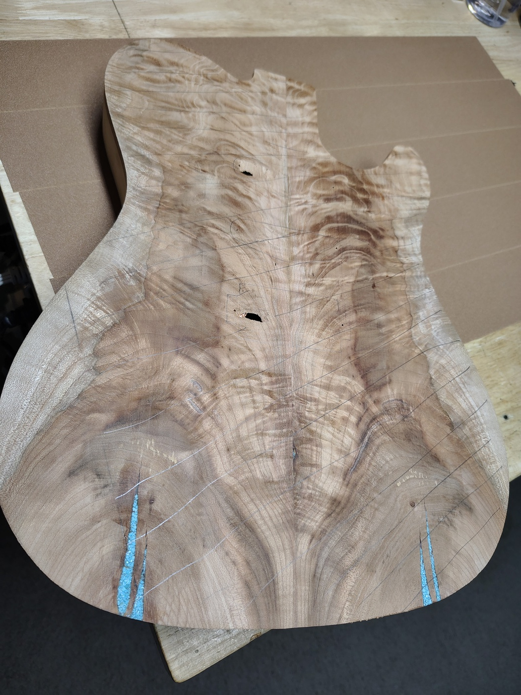
When you get done working out it should look something like this.

Making the pickup mounting rings
Due to the aforementioned unhappy little accident I had to make mounting rings for the pickups and cut normal pickup mounting holes in the top. I could have bought metal or plastic mounting rings (hideous), or used a pickguard (an abomination) but I've found that I can make, what appear to be, all wood pickup mounting rings that look very good. In this case the unhappy little accident turned out to be a happy little accident because the guitar looks better with the pickup mounting rings than it does without. I have this on very good authority - my wife.
Making pickup mounting rings is fairly easy when you have a laser but it's probably faster if you do it by hand with a Dremel router. If you have a laser, here are the Lightburn files (with notes) for making a Strat sized single coil mounting ring and a humbucker sized mounting ring.
If you don't have a laser, here is the scaled (90 pixel/inch) single coil PNG_file and here is the humbucker PNG_file (both were created from SVG files dumped from Lightburn using the above Lightburn files). To use them, print them on paper (to scale of course), transfer that to a 1/4" thick piece of wood (preferably from the drop top blank remains with the grain running in the same direction as the top), Dremel rout the blue portions down a couple of millimeters, then (here's the secret sauce) fill the blue recesses with 5 minute epoxy. When that hardens, drill the holes, cut out the center with a scroll saw, jewelers saw, or jig saw (with a fine blade), then cut out the pickup ring.

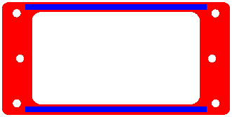
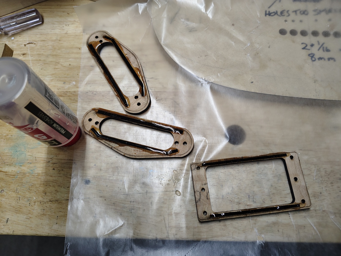
Whether you made them with the laser or by hand you need to sand the bottom of the pickup ring down to remove excess epoxy. When that is done, sand the top down until the ring is about 1/8" thick. I do it the stupid way by holding it against a belt sander (helps with my manicure, do not try this at home) but you could do it with a random orbit sander or by scrubbing it across peel-and-stick sandpaper stuck to a flat surface. You could start with 1/8" thick wood but it wouldn't match the drop top and it would be a bit flimsy until you got the epoxy in it.
Here are the pickup rings before sanding.
Here are the pickup rings after sanding.
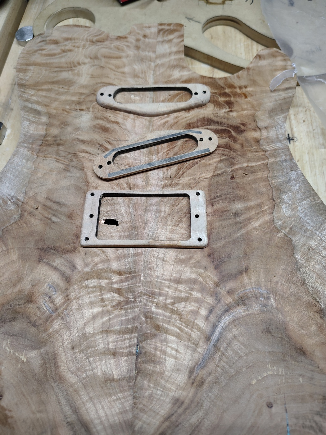
Once they are sanded you can finish them with whatever you are using to finish the guitar. In my case that was CA glue. You can also stain them prior to finishing them if that's what you're doing to the guitar top.
Rounding over the back
I didn't take any pictures of this process because it's essentially the same as rounding over the top except that I used a 1/2" bottom bearing roundover bit. The same advice applies - set the router to the fastest speed, dampen the wood, and bump cut the areas that will be against the grain before you do the final pass.
Making the arm and rib cuts
As you can see from the way I cut the chambers, I didn't leave a lot of wood in the area where the rib/belly cut goes. I'm not a huge fan of the massive Strat belly cut. I prefer a more modest cut that keeps the guitar edge from jabbing you in the ribs. If you want to make one of those huge belly cuts you'll have to leave more wood in that chamber so that you don't sand through when making the cut. Here's the back of the guitar with the rib cut and the sides rounded over.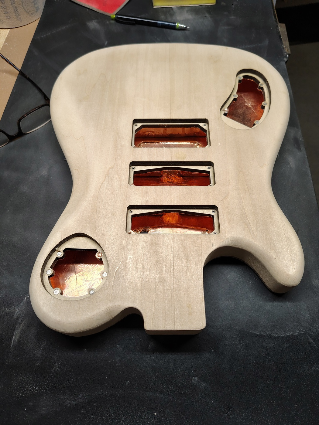
I use an angle grinder with a sanding disk to get the bulk of the wood out of the rib cut and then finish it off with the random orbit sander and hand sanding. I got the angle grinder idea from early Crimson Guitars videos.
I make the arm cut using just the random orbit sander followed by hand sanding (although not much hand sanding). I start with 60 grit to take out most of it and then switch to 120 grit. Here's a picture with the arm cut and the pickup mounting rings sitting on the top (hiding the unhappy little accidents, for the most part).
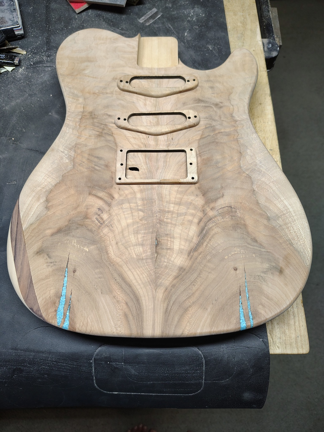
Routing the neck pocket
This is probably the most critical part of building a body. You need to get the neck pocket lined up almost perfectly with the center line so that the bridge and pickups are all in line. Here is a PNG file of the Strat style neck pocket that I use. What I did was make an MDF template with a bunch of different things that I have to rout.

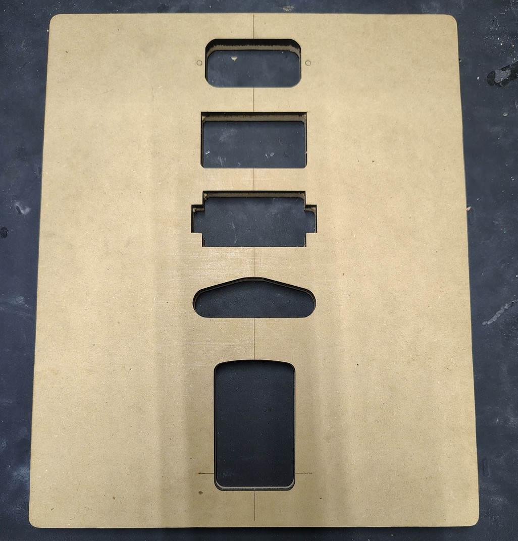
From the top down the templates are for a Fishman Fluence Open Core Classic humbucker (no mounting ring), a standard hardtail bridge (to recess it if required), a standard humbucker, a standard Strat single coil, and the Strat style neck pocket. The other side of the template is covered with peel-and-stick cork that I got from Amazon. If you look at some of the earlier pictures of my drill press you'll see that I covered it (as well as my oscillating drum sander) with the same material. The stuff I bought came from Aecsze (another made up Amazon vendor name) and it's 0.03mm thick. It comes in a bunch of different sizes. The peel-and-stick adhesive is pretty darn good (I know this because I've had to remove it from a couple of things). The cork makes routing very easy since I don't have to worry about trying to protect the surfaces. This is one (and only one) of the reasons that I rout everything else after I've finished the body with CA glue.
Anyway, back to routing the neck pocket. Place the guitar body on a surface you can clamp to (I use my drill press extended table because it's covered in cork), very carefully line up the template center lines and the top of the neck pocket template line with the body, then clamp it in place. Wash, rinse, repeat until it is perfectly lined up. The bottom (towards the bridge) of the neck pocket should be 3" from the end of the neck pocket. Finally, get your router and your set of top bearing flush mount bits and rout the neck pocket down to 5/8". Do this in small increments.
Finishing the body with CA glue
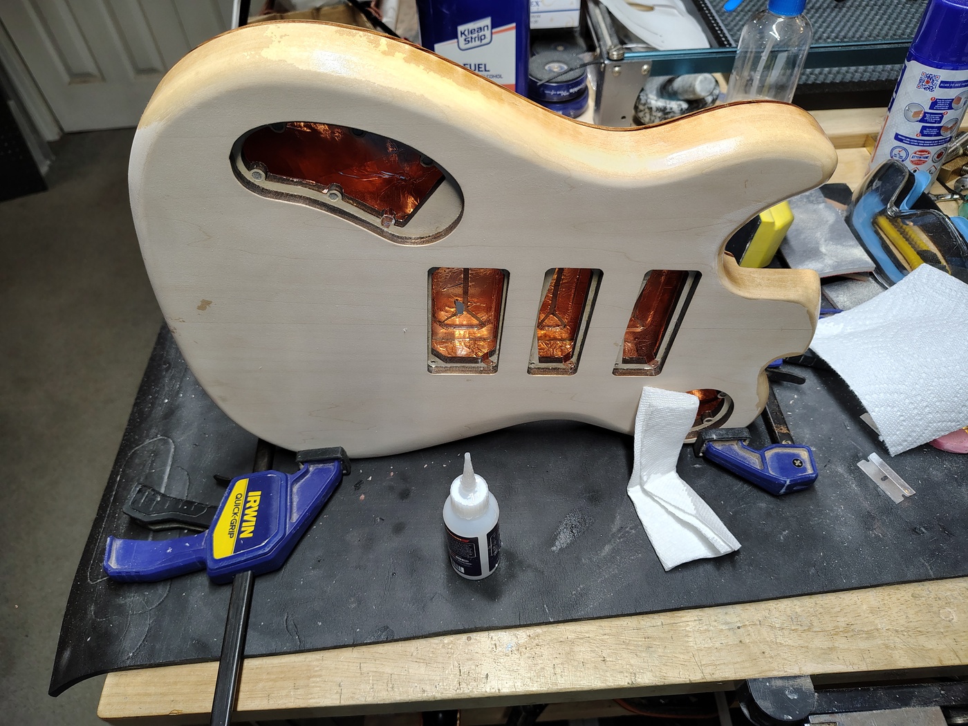
First things first, check the body for dings or deep scratches and then sand it down to somewhere between 320 and 400 grit. Next, wipe it down with denatured alcohol to remove any dust. I'm not going to go into the entire finish schedule here but I will offer one little tip - when working on the sides of the guitar use a couple of clamps on the body, like this:
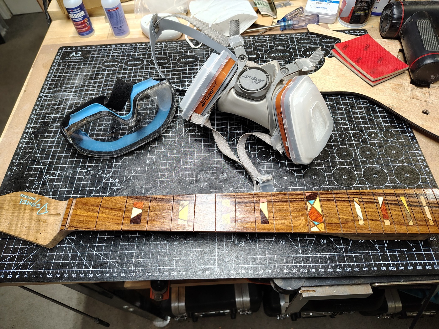
Also, as they say, safety fourth. That is what they say isn't it? Oh well, better late than never. If you're going to work with CA glue you need goggles and a P100 respirator because this stuff will burn your eyes and breathing the fumes is not advisable. Don't worry, they're not expensive. These are the ones I use although I'm looking at a pair of bifocal UVEX by Honeywell goggles so that I don't have to wear reading glasses under the goggles.
To see the rest of the finish schedule (which requires a page of it's own) just go to Sanding and finishing.
Routing the pickup cavity holes in the drop top
This is something that is a bit out of whack with what most people do. The common "knowledge" available on the internet says never, ever, ever rout the pickup cavities after you've finished the guitar. Why? Because you'll crack the lacquer. Lucky for us, we're not using lacquer (so we don't have to wait two to three weeks for it to "cure" either). CA glue doesn't chip easily (and it "cures" in about 10 minutes). Another major advantage to doing it this way is that you only have to deal with the neck pocket edges on the top. Finishing, and especially sanding the finish, is difficult at sharp edges. By finishing first we've avoided that problem.
There is one caveat though, you need to cover the back side of your templates with cork (or felt, although that can get messy). Place the body on a flat surface that you can clamp to (as stated before, I use my drill press extended table which is covered in cork). Position the template over one of the pickup positions. Just like with the neck pocket this needs to be precise if you're back mounting the pickups because you've already cut the back plate covers out of the back. If you didn't go with back mounting the pickups you can afford a little drift but not much. Once the template is in place, clamp it down and check it again. Wash, rinse, repeat until it's right. Then rout out the cavity.
Do that for however many pickups you have, et voila!
Positioning the neck and drilling the holes in the neck pocket
Position the neck plate one the back of the body over the neck pocket. You can look at pretty much any Fender Strat or Tele online to see where the plate should go. Mark the holes and then drill them through the neck pocket using a bit that is slightly larger than the threads on your neck screws. You don't want the neck screws threading into the body, only into the neck. Place masking tape over the estimated location of the bridge. Place the neck in the neck pocket and line it up with the center line of the guitar. Clamp it in place (use a deep throat clamp with good padding, I use those little round slide pads for furniture stuck on the clamping surfaces). There are some nifty tools to help you line up the neck with the body but they cost about $90. I just use a straight edge on each side of the guitar. I place a piece of masking tape across the approximate position of the bridge, mark the center line, draw a line perpendicular to that, mark where the straight edge hits in relation to that center line on each side, then measure those distances. When they're the same, the neck is centered. At that point you have to VERY CAREFULLY, without moving the neck, put something through the neck holes to mark the location of the screw holes. I have an old small screwdriver that perfectly fits the hole size I use.
Once the locations are marked, remove the neck, put the screws through the neck plate and the neck pocket to see how deep you have to make the screw holes in the neck heel. Make the screw holes in the neck heel using a drill press to keep them straight. If you're using roasted maple (like I did) don't make the holes too small because roasted maple is very brittle and can split easily. Partially screw the screws into the holes in the neck heel to get them started. Read the following then attach the neck to the body and see how it came out.
Important note: once you've screwed the neck screws into the neck and removed them you need to make sure that every time you reattach the neck you insert the screws and then turn them counterclockwise (or lefty loosey for the analog clock challenged) until you hear and/or feel a "click", for want of a better word. Once you hear/feel the click you can then screw the screws in. What this does is realign the screw threads with the indentations of the screw threads in the hole. That way you don't end up stripping out the hole. This is analogous to screwing the top on the peanut butter jar backwards to align the threads before you tighten it down. You should do this with all screws in wood or plastic.
Positioning the bridge
Ah, the arcane knowledge! This is actually very simple. The first thing you have to know is the scale length of your neck. In my case it's 24.07" but it could be 24.75", 25", 25.5", or anything else. The easiest way to check is to measure from the front face of the nut (or leading edge of the nut slot) to the center of the 12th fret (or fret slot) and multiply that by 2. Once you know that you simply attach the neck and measure that distance from the nut down onto the body and mark it. It's best to cover this area with some masking tape and then also mark the center line on the tape.Now, on to some physics. I have seen advice on the all powerful internet that you should place the center of the saddle travel at the scale length distance from the nut. That makes absolutely no sense. If we had a guitar string that was crazy small (like one atom in thickness) then we would want the the point where the string touches the bridge saddle for that string to be at exactly the scale length distance from the bridge. Now, the smallest string we have is the high E string and it will be .009, .010, or something on that order. Because the string actually has some thickness and becomes effectively longer when we fret a note, the saddle location will always be farther away from the nut than the scale length (assuming you want correct intonation). This is why you would never put the center of travel of the saddles at the scale length - you will never have to move a saddle closer to the nut than the scale length. So, what's the answer? I have seen a number of compensation advice on how far back the low E and high E strings have to be but you're never going to get it exactly right. This is why we have adjustable saddles (it's different on an acoustic guitar but there are still better ways to check the intonation than using a preset number). What I do is move the high E string saddle as far forward (towards the nut) on the bridge as it can go and line that location up with the mark for the scale length distance from the nut. I know before I start that I'll have to move it back a small amount but I also know that I won't ever be too far forward. This also gives me the most amount of play for adjusting all the other, thicker strings (which will all be farther back than the high E).
Once you've got the location set and the bridge squared up, mark and drill the holes then attach the bridge.
Making the custom volume and tone knobs
Here's another fun thing to do. Of course, you can buy knobs on Amazon to save some time. You can even buy wood knobs on Amazon and they're pretty good. I just happen to like making my own knobs so I thought I'd outline the steps here.
First thing you need to know to do this is where to get the knob inserts. The company that I use is called Love My Switches. The have brass inserts with set screws. I don't use their set screws for two reasons. First, I don't like common screwdriver screw heads. Second, brass heads strip out too easily. You can get stainless steel, flat head, hex socket M3 x 3mm set screws on Amazon. for about $6. They never strip and it's much easier to get the set screw into the hole in the side of the knob with a hex head wrench (also known as an Allen wrench).
On to building the knobs. I have been making them using my laser but each time I make them I do less and less with the laser and more with normal tools. It's faster and you get a better product that way. You can make the knobs out of two pieces, or three pieces. I wouldn't try one piece because after you fit the insert you can't get it back out again if it's not in the exact right place. I'm going to cover making them in three pieces. I like the knobs to be 19mm tall and 19mm in diameter. I always make the lowest layer out of 1/4" (6.35mm) basswood. That makes it easier to get the inserts in and out.
The first thing you need to do is mark a 20mm circle on a piece of 1/4" basswood. In the middle of that circle you need to mark a 16mm circle. The 16mm circle needs to be recessed by 3mm. The easiest way is to use a Dremel router. It doesn't have to be perfect as this will be the underside of the knob and nobody will ever see it. We're just making clearance for the washer(s) and nut. Once that is done you need to drill a 10mm hole through the dead center (as they say at the Haunted Mansion) of the inner circle. Once that is done you can cut out the outer circle. This will be the base of the knob.
Next you need to make the middle layer. I used a 1/4" (6.35mm) piece of Bolivian rosewood. Mark a 20mm circle and then put a 10mm hole in the dead center of the circle. When that's done, cut out the circle.
The last piece is the top and it's just a 20mm circle of 1/4" (6.35mm) wood. It doesn't need a hole or a recess so you can just cut it out. I used some of the drop top wood. Granted, I cheated and used my laser to make some inlays but you can do something like that with a Dremel router and a 1/42" spiral router bit if you're careful.
Now that you have all three pieces you need to glue the base and the middle together. I've been using medium CA glue but it dries so fast in wood that there is very little working time. I think that I will probably switch to wood glue in the future. I'll have to let it set up overnight but that's OK. Patience is a virtue and when you're making a guitar patience and thinking are your two best tools.
Once the base and middle are solid you can measure and figure out where you need to dill the 1/8" hole in the side for the set screw. The base of the insert needs to end up flush with the internal recess in the base. I've found that once I've got the spot marked I can just put the (almost) knob in a clamp, lay it down flat, and drill the hole by hand.
After drilling the hole you need to screw the set screw all the way in to the insert so that it doesn't stick out on the outside of the insert. Next you need to try to align the set screw with the hole in the knob and push the insert in. If it's not right you can push it back out again from the top (this is why I don't make one piece knobs). Once you have it lined up, take the set screw out, put a bit of wax on it, put it back in all the way, put the insert in the knob, and then put a few drops of thin CA glue around the insert - NOT ON THE SIDE WITH THE SET SCREW. If you mess up and get some on the set screw the wax should keep it from sticking.
At this point we almost have a knob. We now need to glue the top on. Again, I'd use wood glue so you can get it straight. Let it set overnight.
The more astute may have noticed that the diameter is 20mm. The reason for this is that nobody ever cuts a perfect circle. This is where the fun comes in. Find a round 1/4" drill bit, stick it, base first, into the insert and crank down the set screw, then chuck it into your drill press (or drill, that will work too but it's a bit more cumbersome).
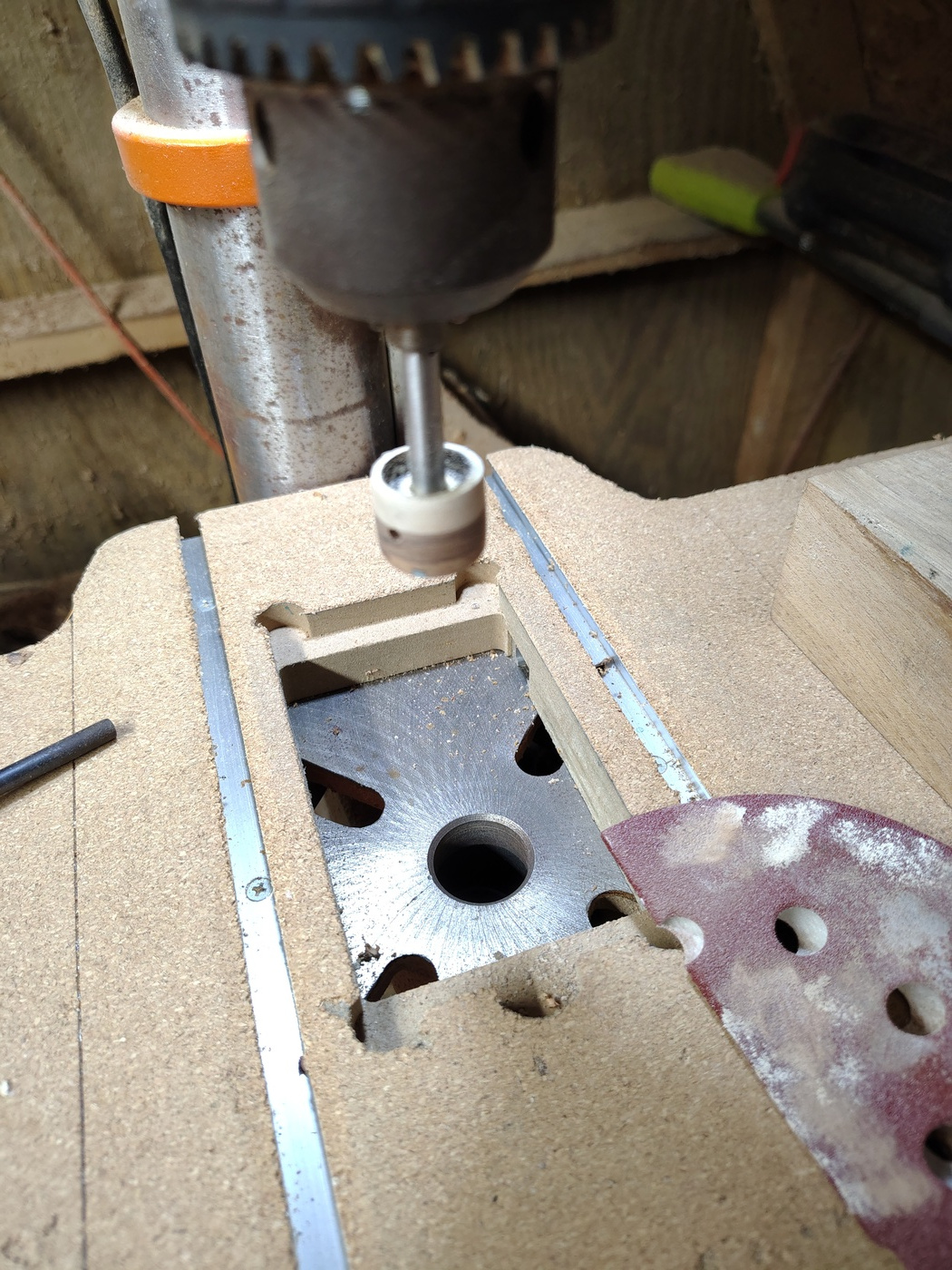
Using a hard flat backing piece and some 120 grit sandpaper, sand the knob down to 19mm. This will make it almost perfectly round. Don't forget to round over the top. Once that's done, switch up to 220, and 320 grit to smooth out the scratches. Next, do the same finishing process that you did with the body but use Q-Tips to apply the CA glue. You can put the knob on an old potentiometer to hold it while you coat it with CA. After it's dry with all six coats on it use a 220 or 240 grit soft sponge sanding block to flatten out the finish by hand. Follow up with 320 grit and 0000 steel wool. After the steel wool you can go on and do the same levels of finish sanding and polishing that you did for the body but with one last trick to make it much faster and easier. Chuck the knob into a drill and use it to do the final sanding and polishing.
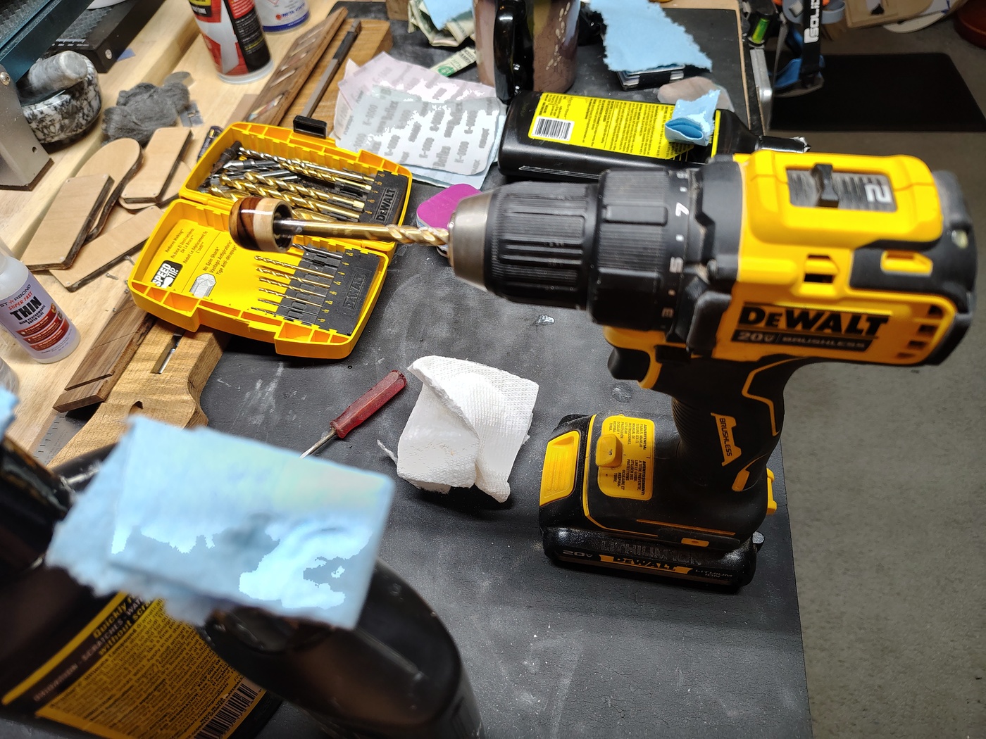
Love My Switches also has brass sleeves for putting this type of knob on potentiomenters with knurled shafts.
Drilling the potentiometer, switch, and jack holes
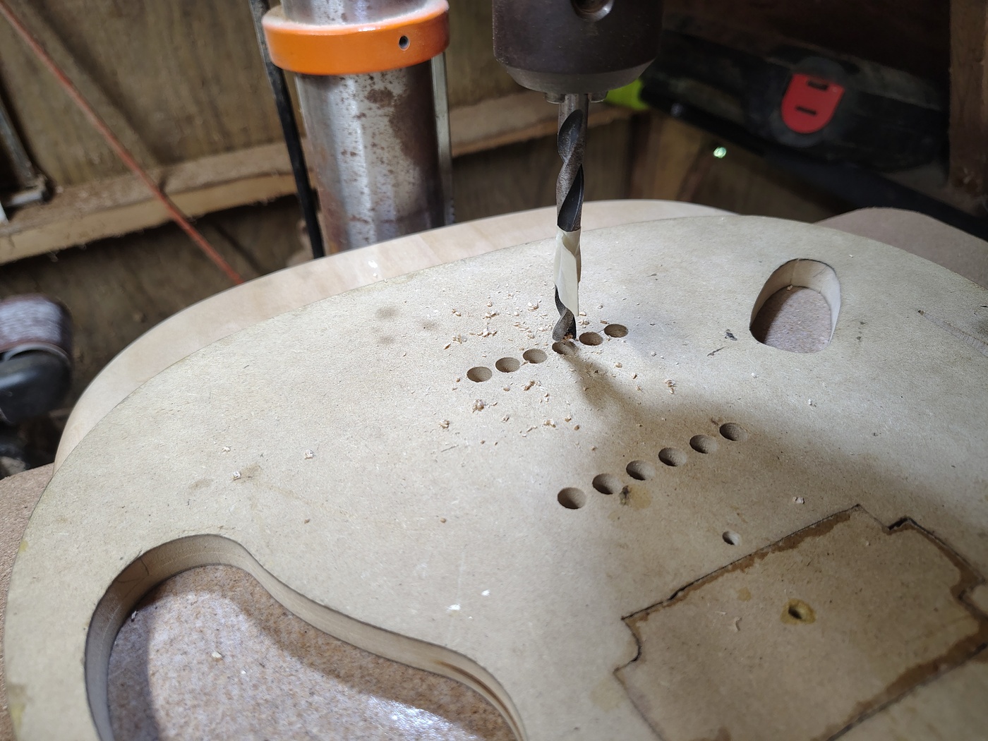
The first thing you need to do is figure out where you want to put the knobs and switch. The easiest way to do this is to open the control cavities and see how things fit. Once you've got that straight just drill 1/16" holes in the top from inside the guitar in the locations where you want the pots and switch. It's best to do some measuring and double check where they'll end up on the top before you drill the holes. Once you have drilled the holes just drill through from the top with brad point bits of the correct size. Here's a little tip - when drilling the holes in the top, start by running the drill slowly in reverse to make a nice clean cut around the outside of the hole. Once it's clean, flip it back to forward and very slowly drill through (thanx and a tip of the hat to Ted Woodford - you can find him on YouTube). Yet another tip - if you're putting pot shafts through a 1/4" top you need long shaft pots. Short shaft pots are made for pickguards.
The jack hole for most 1/4" jacks needs to be 7/8" in diameter but check what you've got before you drill. I highly recommend getting Pure Tone jacks so that you'll never have any connection issues. They're a bit more expensive but well worth it. If you look at the TIFF file I provided earlier you can see in the Rout layer that I have a bulge in the side in the potentiometer control cavity. That's where I like the jack to go. I have a specific reason for this. On the original Telecasters they put the jack closer to the bottom of the guitar. I'm not sure why although there is a possibility that they were trying to keep the plug from being pulled out if you stepped on the cord. If that was the thinking, it was not a very good idea for three reasons. First, instead of pulling the cord out, which is annoying but easily remedied, you would possibly snap the plug off or bugger your jack (not easily remedied). Second, everyone who has ever played on stage wraps the cord over the bottom strap button to prevent either of those things happening. Third, and to me the most annoying, is that if you try to set the guitar down on a normal guitar stand (and, yes, I'm including the little portable Fender stands that I love) the plug is directly in the way. To remedy that I just moved the jack a little north.
Drilling the string through body holes
There are a number of templates you can get that have holes lined up for the string through body holes. What they don't always tell you is that the string spacing may be 2 and 1/16", 2 and 1/8", or many other variations. If you've bought a string through body bridge you have in your hands the absolutely perfect template. Just attach the bridge and do what comes naturally.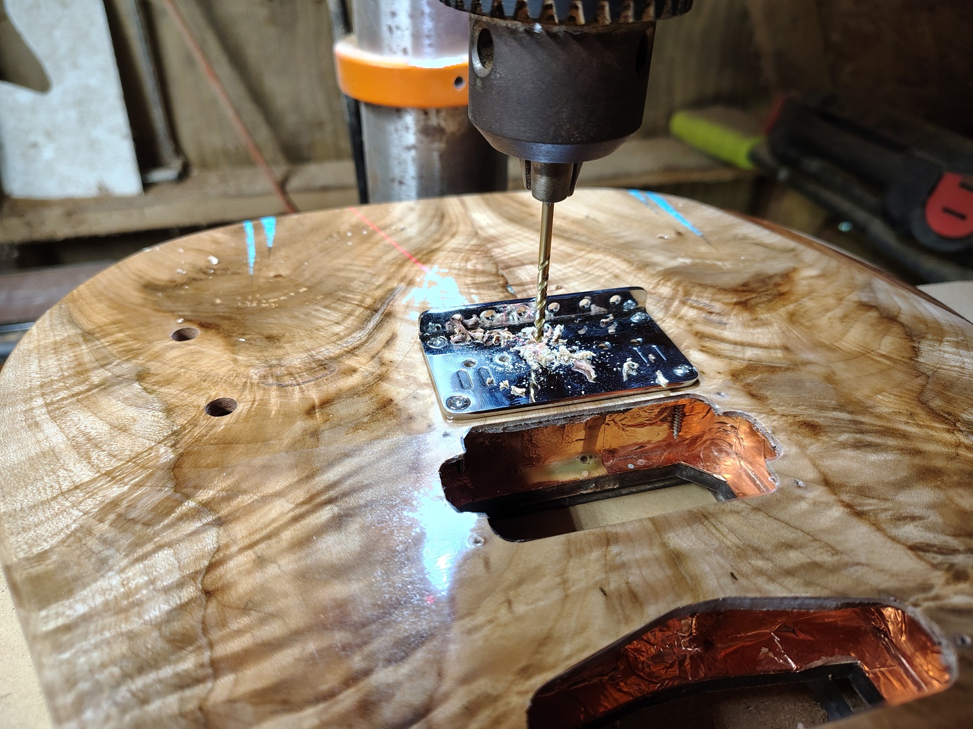
Oh, look, another happy little accident. If you look inside the humbucker rout you can see that the front bridge screws missed the basswood block that they should have gone into. So, obviously, my template layout was wrong. DOH! Since those screws are going in to 1/4" of hard maple they aren't going anywhere. Plus, the pressure on those two screws is in the down direction. Anyway, here's the happy part - the screws are slam up against (and also partially through) the copper foil tape. That means that I didn't have to drill and run a bridge ground wire since all of the copper foil is connected to ground. If you didn't have this happy little accident you need to drill a 1/8" hole from under the bridge to the bridge pickup cavity to run a ground wire.
Drilling the string ferrule holes
For the string ferrules you will need to make or buy a template. Trying to do it freehand is a disaster (I know, I tried it once). Generally speaking the knurled ferrules usually require 8mm holes but measure what you've got before you make or buy a template. Also make sure the string spacing is what your bridge has.
To pickguard or not to pickguard
That's not really a question. Especially if
you've dropped over $100 for a beautiful figured drop top.
Why the heck would you want to cover it up? On the other
hand, you need something to keep the top from getting torn
up. What's a poor luthier to do? Well, StewMac has some
clear pickguard material that sells for an arm and two
legs. The problem is that it's 20mil thick and looks more
translucent than transparent (I bought some and threw it
away). At some point in the past I had found a purveyor of
laminating sheets that were 7mil thick. Those things
worked great. Unfortunately, they no longer sell them. So,
I had to go on a laminating sheet buying spree to try to
find something that was close. I won't bore you with the
10 or so failures but I will give you a link to the winner.
Now, since it's Amazon, I'm sure that link will die
eventually so here is the seller and product - LA
LLAMA, Self Adhesive Laminating Roll 12” x 15ft - 5 MIL
Multipurpose Clear Laminate Vinyl Roll for Stickers.
It works great. I've used it on 4 or 5 guitars and haven't
had any problem with it. If you find it on Amazon check
the reviews. Mine is usually first with images of one of
my guitars. I think that's possibly because it's such a
weird use for laminating sheets (and maybe because I'm so
verbose... Nah, that couldn't be it).
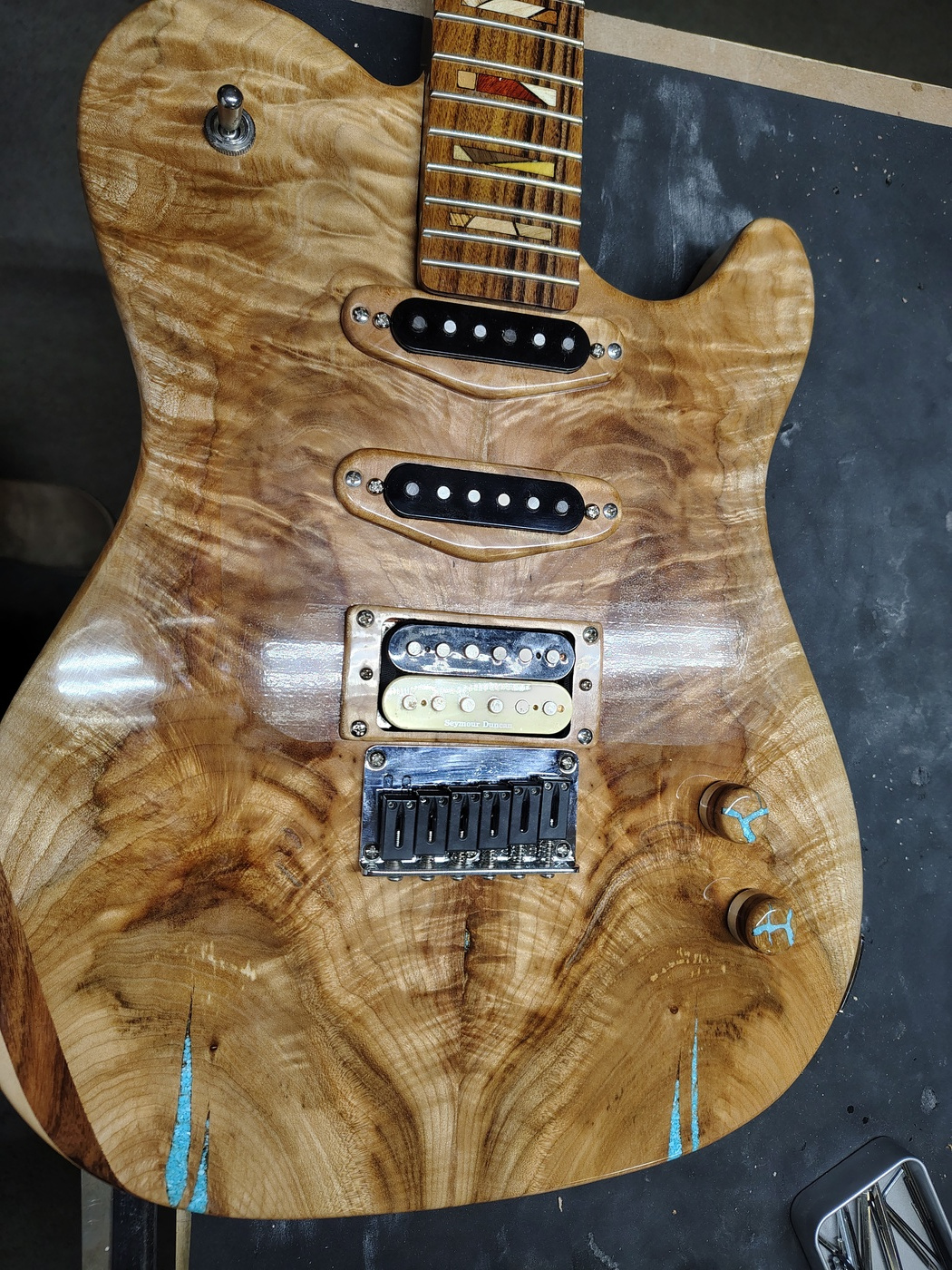
From this angle you can see some of the pickguard but from the front it's almost invisible. Also, after a while, the pebbly nature sort of calms down.
You can use the Pickguard layer in the design TIFF to get a reasonable pickguard shape or you can just draw one by hand on paper and cut it until it fits. Then you can transfer that to the back of the laminating sheet (don't forget to do it backwards). Once it's transferred cut it out from the back because this gives you the correct angle on the edges of the sheet. I'm not going to explain how it's done because I got it from Frank Ford on YouTube.
There is one difference between what we do and what Mr. Ford was doing. We have to deal with pickup routs. I used to try to make the pickguard with cutouts for the pickup routs. That was like trying to make boiled spaghetti stand up straight again. It went all wobbly and was super hard to get down flat. I finally realized that there is no point in going through that. Just make the pickguard in one piece, cover the pickup routs, and then, after it has thoroughly dried, cut out the pickup routs with a box cutter. I found some really good box cutters on Amazon. Of course, this link will probably disappear at some point so here's the name to search for on Amazon - Nicpro 15 Pack Utility Knives with 30 PCS Extra Blades, Plastic Box Cutters. Less than $1 apiece plus you get 30 extra blades.
Installing hardware
There's not much involved in installing the
hardware. You should have already attached the bridge so
that's half the battle. When you install the pickups you
should slide them around a bit to get them in the center
of the pickup cavity, try to keep them straight, and make
sure that you haven't left a gap anywhere around the
edges. Once they're where you want them, use an awl or a
center punch to mark where the holes go. Remove the pickup
and then drill the holes. As stated above, if you remove
the screws at any later time, rotate them counterclockwise
until you hear the click before you screw them back in.
Before you drill the holes for the jack
plate, attach the jack and then test fit it in the hole.
Try to keep it from pushing against the side of the hole.
Once it's in place, mark the holes, remove it, drill the
holes, and then attach it.
Strap buttons just require decent
positioning. The design TIFF has a location marked for the
upper bout button but it's not written in stone where it
goes. One thing about the strap buttons - if you've made a
basswood body make sure that the holes are smaller than
you normally would make them. Basswood compresses easily
so the screws will go in easily even with a smaller hole
plus, they'll hold better that way.
Now, on to the hardware I used for this
build. The bridge is just a generic 2 and 1/16" string
spacing string through body hardtail bridge. I got it on
Amazon and there must be 50 different brands. I like 2 and
1/16" spacing because it helps keep the high and low E
strings farther from the edge of the neck.
I always use Dunlop Straploks for my strap
buttons. They're easy to use, you'll never drop your
guitar, and they don't squeak like the Schaller style
locks. But that's just my preference.
The pots are Musiclilly A250K long shaft
push/pull pots. Nothing special.
The pickups are really interesting.
Backstory - I hate the sound of Telecaster pickups. They
sound like audio razor blades. I've always loved the sound
of the Strat neck pickup and I recently learned that I
very much like the sound of the Strat middle pickup by
itself. That being said, I detest single coil pickup hum.
While perusing the interwebs I stumbled upon Tonerider
pickups. Designed in the UK, made in China, zero hum, and
theyre supposed to sound just like normal Strat pickups
without the hum. I tried out an Apex Classic neck and
middle pickup and an Apex Plus bridge pickup. They weren't
lying, they sound just like Strat pickups without the hum.
Plus, they only cost $65 apiece. After playing with them
for a while I decided that I didn't like the Strat bridge
pickup sound so I used a Seymour Duncan StagMag (or SH-3)
for the bridge. This isn't a normal humbucker. It doesn't
have a big slab magnet underneath the coils. It is,
essentially, two Strat single coil pickups affixed side by
side with one of them having reverse polarity and being
reverse wound. It gives me a very nice humbucker sound but
it's a bit less low end heavy.
I'll go ahead and cover the tuners here
instead of in the Building a
neck section. I had been using Fender locking tuners
and recently tried Guyker's locking tuners and I liked
both (Guyker makes some very good hardware at reasonable
prices) but I finally decided to take the plunge and try Graphtech's
Ratio tuners. I'll never use anything else. They're
about $40 more than the Fender locking tuners but, if you
play live, they're worth the difference. Tuning,
especially the low E string and the G string, is
incredibly smooth and easy. I got mine on Sweetwater
because you get a two year warranty and they're less
expensive there.
As far as wiring is concerned, check out
the Wiring page.
Copyright © Jan Depner 2026 - All rights reserved